




Where Are Steel Pipe Piles Used in Bridge Foundations?
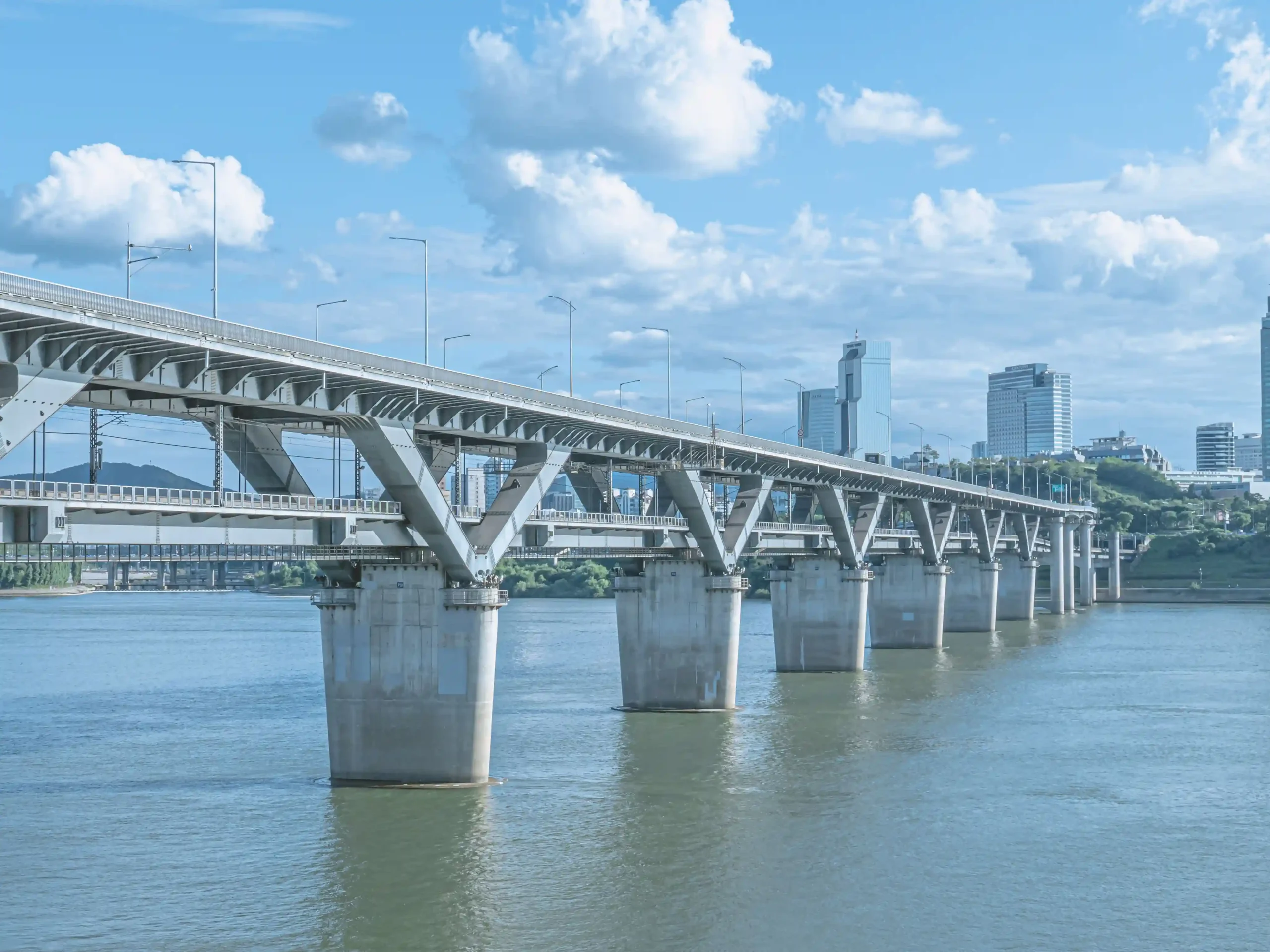
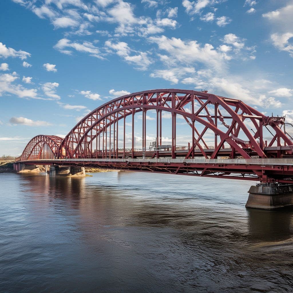
Steel pipe piles are used in bridge foundations where deep load transfer and reliable structural support are required. Their applications mainly include bridge piers, abutments, and structures crossing rivers or coastal waters.
Bridge Pier Foundations
Steel pipe piles are commonly arranged in groups beneath bridge piers and connected by reinforced concrete pile caps.
According to the FHWA, large-diameter pipe piles exceeding 36 inches (914 mm) are frequently considered for major bridge piers requiring high lateral resistance. One documented FHWA example uses 42-inch (1,067 mm) diameter spiral-welded open-ended piles for a main bridge pier.
Bridge Abutment Foundations
Bridge abutments support bridge spans and retain approach embankments. Steel pipe piles are used where shallow soils have insufficient bearing capacity or excessive compressibility.
For reference, the South Carolina DOT Bridge Design Manual identifies 16, 18, 20, and 24-inch (406, 457, 508, and 610 mm) pipe piles with 1/2-inch (12.7 mm) wall thickness as typical sizes in its design practice. Actual dimensions depend on project loads and geotechnical conditions.
River and Marine Bridge Foundations
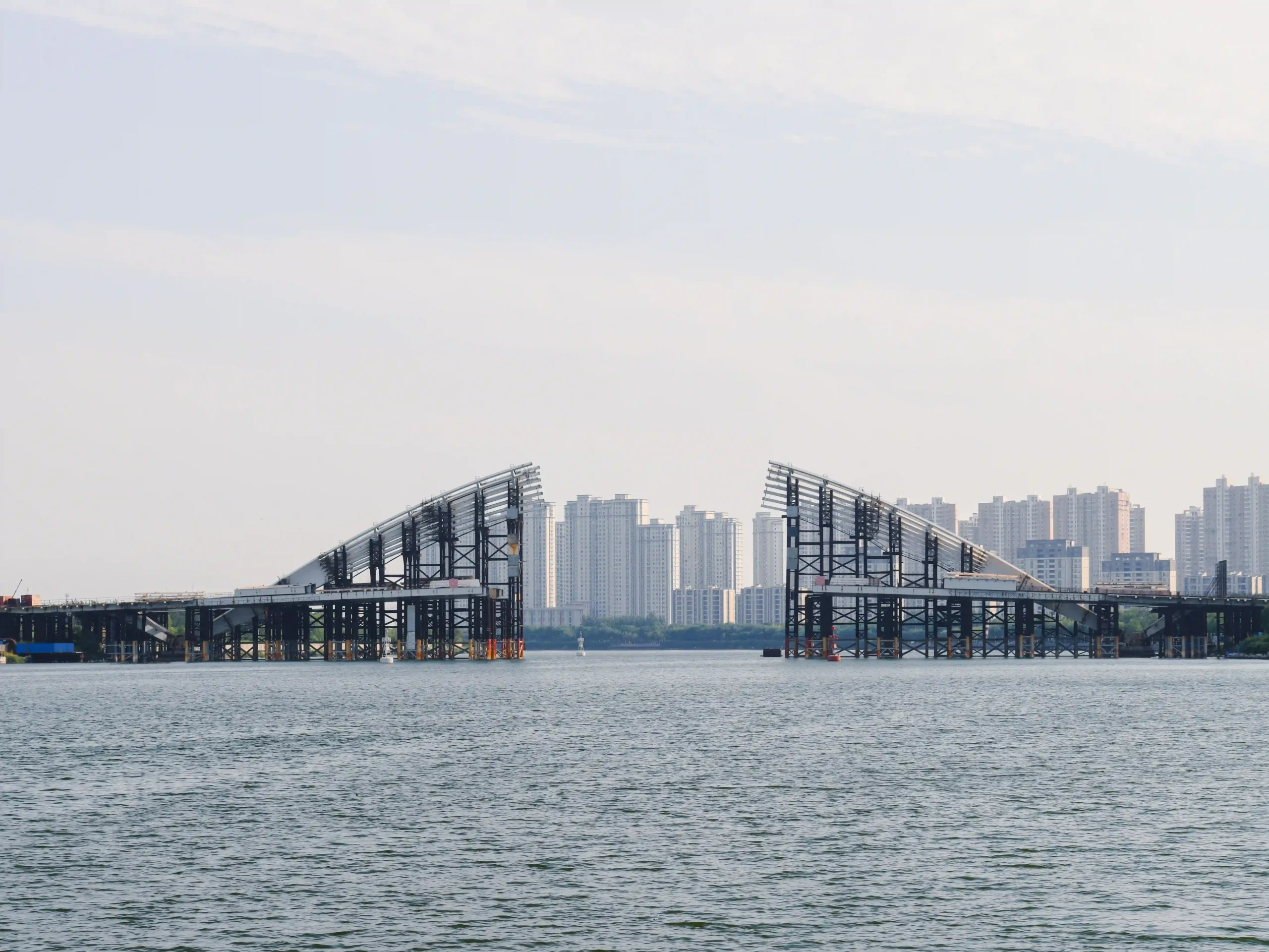
For river and marine bridges, steel pipe piles are installed into riverbed or seabed soils, where foundation design must account for water depth, soil conditions, scour, and corrosion.
A documented Richmond–San Rafael Bridge seismic retrofit used large-diameter foundation piles measuring 3,200–4,110 mm in diameter, with wall thicknesses of 38–57 mm. Installation extended to elevations of approximately 42.7–67.1 m below the project datum, in water depths of up to 21 m.
How Do Steel Pipe Piles Support Bridge Structures?
Steel pipe piles support bridge foundations through three main functions:
- Axial Load Transfer
- End Bearing: Transfers vertical loads through the pile toe to dense soil or rock.
- Skin Friction: Transfers loads through contact between the pile surface and surrounding soil.
- Combined Resistance: Both mechanisms contribute to the pile’s overall axial load capacity.
- Lateral Load Resistance
Bridge foundations must resist horizontal forces generated by water currents, wind, vehicle braking, and seismic activity.
The circular tubular section provides bending resistance and structural stiffness. Its performance depends on pipe diameter, wall thickness, steel grade, pile embedment, and surrounding soil conditions.
- Pile Groups and Pile Cap Connections
Multiple steel pipe piles are commonly connected by reinforced concrete pile caps to support bridge piers and abutments.
| Component | Function |
| Pile Cap | Transfers structural loads to individual piles. |
| Pile Group | Distributes vertical loads and resists lateral forces and overturning moments. |
| Pile Spacing | Influences load distribution and interaction between adjacent piles. |
| Pile Connections | Provide effective load transfer between steel piles and the concrete cap. |
Types of Steel Pipe Piles for Bridge Foundations
Steel pipe piles can be classified by their pile toe configuration and internal filling condition. Open-ended and closed-ended piles are the main toe configurations, while concrete-filled and hollow piles describe their internal structure.
Open-Ended vs. Closed-Ended Steel Pipe Piles
The main difference is how the pile toe interacts with the surrounding soil during installation.
| Comparison | Open-Ended Pipe Piles | Closed-Ended Pipe Piles |
| Pile Toe | Open bottom | Sealed with an end plate or pile shoe |
| Soil Entry | Soil can enter the pipe | Soil cannot enter through the toe |
| Soil Plugging | An internal soil plug may develop | No internal soil plug forms through the closed toe |
| Soil Displacement | Generally lower when unplugged; increases as plugging develops | Generally greater during penetration |
| End Resistance | Depends on plugging condition and toe resistance | Developed through the closed toe |
| Driving Resistance | Influenced by external and internal shaft resistance and plugging | Influenced by toe resistance and soil displacement |
| Toe Details | Open toe without a bottom plate | Requires a designed end plate or pile shoe |
Open-Ended Steel Pipe Piles
Open-ended piles have an unsealed bottom, allowing soil to enter the pipe during driving. Soil plugging is an important consideration because it affects penetration resistance and the pile’s end-bearing behavior. This configuration is commonly considered for deep foundation applications.
Closed-Ended Steel Pipe Piles
Closed-ended piles use a welded end plate or fabricated pile shoe to seal the bottom. The closed toe displaces soil during driving and transfers load through the pile base. End plate design and driving resistance must be considered during pile selection and installation planning.
Concrete-Filled Steel Pipe Piles
Concrete-filled steel pipe piles combine a steel tubular shell with an internal concrete core. The combination provides composite structural performance, with concrete contributing to compressive resistance and the steel shell providing structural strength and confinement.
Hollow Steel Pipe Piles
Hollow steel pipe piles retain an empty internal section without concrete filling. They are suitable where the steel tubular section meets the structural requirements. They can also be designed with either open or closed ends.
Steel Pipe Pile Specifications and Material Requirements
Steel pipe pile specifications for bridge foundations depend on structural loads, geotechnical conditions, installation methods, and project standards. The main procurement parameters include pipe dimensions, steel grade, pile length, and connection details.
Diameter and Wall Thickness Selection
Outside diameter and wall thickness influence the structural performance of steel pipe piles.
- Larger Diameter:Can improve bending stiffness and resistance to lateral loads.
- Greater Wall Thickness:Increases section strength and provides additional resistance to local buckling and installation stresses.
ALLLAND’s manufacturing ranges include:
| Manufacturing Process | Outside Diameter | Wall Thickness |
| LSAW Steel Pipe | 406–1,524 mm | 6–60 mm |
| SSAW Steel Pipe | 219–3,500 mm | 5–25 mm |
These are manufacturing capabilities, not universal design recommendations. Final dimensions must be determined by structural and geotechnical design.
ASTM A252 Grades and Material Properties
ASTM A252/A252M is a commonly used product specification for welded and seamless steel pipe piles. It covers three grades with different specified minimum mechanical properties.
| Grade | Minimum Yield Strength | Minimum Tensile Strength |
| Grade 1 | 30 ksi (205 MPa) | 50 ksi (345 MPa) |
| Grade 2 | 35 ksi (240 MPa) | 60 ksi (415 MPa) |
| Grade 3 | 45 ksi (310 MPa) | 66 ksi (455 MPa) |
Grade 3 offers the highest specified minimum yield and tensile strengths among the three grades. The final grade should be selected according to structural calculations, welding requirements, and project specifications.
Steel Pipe Pile Length and Splicing Requirements
Pile length is determined by the required penetration depth, soil profile, bearing stratum, and foundation design loads. For deep bridge foundations, multiple pipe sections may be joined to achieve the specified installation length.
| Parameter | Key Requirement |
| Pile Length | Based on geotechnical investigation and required embedment depth. |
| Section Length | Considers transportation, lifting, and installation conditions. |
| Splicing Method | Commonly uses circumferential welding. |
| Joint Quality | Requires appropriate welding procedures and joint alignment. |
| Inspection | Visual inspection and specified NDT, such as UT or RT, according to project requirements. |
Applicable Bridge Foundation Design Standards
The applicable standards depend on whether the requirement concerns pipe materials, bridge design, installation, or welding.
| Standard or Reference | Main Application |
| ASTM A252/A252M | Steel pipe pile product requirements |
| AASHTO LRFD Bridge Design Specifications | Bridge structural and foundation design |
| FHWA Driven Pile Foundations Guidance | Driven pile design, installation, and quality control |
| AWS D1.1/D1.1M | Structural steel welding, where applicable |
Project-specific requirements and applicable editions should always be confirmed before production.
Bridge Foundation Challenges: Scour, Soil and Water Conditions
Unlike conventional building foundations, bridge foundations in rivers and coastal areas are exposed to riverbed scour. Flowing water removes soil and sediment around bridge piers, which can affect steel pipe pile foundations in several ways:
- Reduced Soil Support:Scour removes surrounding soil and reduces lateral support for embedded piles.
- Increased Exposed Length:A lower riverbed level exposes more of the pile shaft, increasing bending demands.
- Foundation Stability:Remaining pile embedment and structural capacity must be evaluated under anticipated scour conditions.
Reference: FHWA, HEC-18: Evaluating Scour at Bridges, Fifth Edition.
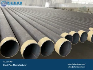
ALLLAND manufactures large-diameter, heavy-wall LSAW and SSAW steel pipes for demanding bridge foundation applications. With customizable steel grades, wall thicknesses, pipe lengths, and end configurations, our products can be tailored to project-specific structural and installation requirements. We also provide 3PE, 3LPE, 3LPP, and FBE coating systems to help protect steel pipe piles against corrosion in freshwater and marine environments.