Welcome to ALLLAND Steel Pipe Co., Ltd.
ALLLAND Steel Pipe Supply
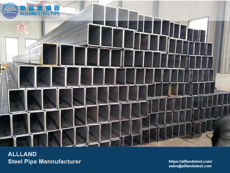
Welcome to ALLLAND Steel Pipe Manufacturing. EN 10217 in engineering applications involving pressure conveyance systems, the inherent stability and safety of steel pipes are critical to the overall performance of the system. To meet the demands of such applications, ALLLAND offers pressure-rated welded steel pipes that comply with the EN 10217 standard. In addition to providing EN-compliant products, we place a strong emphasis on tailoring manufacturing processes, material delivery conditions, and corrosion protection strategies to meet the specific operating conditions of each customer’s application, thereby ensuring a reasonable balance between system safety and engineering cost control.
Alllandsteel is a steel pipe manufacturer based in China with 25 years of experience.
The facility spans 22,000 square meters, represents a RMB 700 million investment, and operates four production lines (JCOE, ERW, SMLS, SSAW) alongside five coating lines.
With an annual production capacity of 250,000 tons, the factory covers specifications ranging from Ø406 to Ø1524 and holds multiple international certifications (API/ASTM/EN/ISO/JIS). Focused on steel pipes, creating value for you!
HOT PRODUCTS
POPULAR ARTICLES
EN 10217 is one of the core European standards for welded steel tubes, primarily intended for pressure applications such as boilers, pressure vessels, and transmission pipelines.
Its full title is “Welded steel tubes for pressure purposes—Technical delivery conditions.”
O.D.:
ERW / HFW:21.3 mm – 660 mm
LSAW:406.4 mm – 1422 mm
SSAW:219 mm – 3500 mm
W.T.:
ERW: 2.0 – 20 mm
LSAW: 6 – 50 mm
SSAW: 5 – 25 mm
Length:
6 m/ 12 m /Cut to length
Manufacturing Process:
ERW / HFW/ LSAW/ SSAW/ TIG / Laser
Standard Composition:
EN 10217-1、EN 10217-2、EN 10217-3、EN 10217-4、EN 10217-5、EN 10217-6、EN 10217-7
Delivery Conditions:
+N(Normalized)
+AR(As rolled)
+M(Thermomechanical rolled)
EN 10217 specifies non-alloy steel welded tubes for use in pressure-bearing applications, suitable for high-temperature, ambient-temperature, or low-temperature conditions.
It is divided into the following sections based on material and properties:
1. EN 10217-1: Non-alloy steel tubes
Common steel grades:
· P195TR1 / TR2
· P235TR1 / TR2
· P265TR1 / TR2
EN 10217 specifies two technical delivery conditions:
TR1—No impact testing required
TR2—More stringent requirements (Including impact testing)
2. EN 10217-2: Non-alloy & alloy steel tubes for elevated temperature (High-temperature applications)
Common steel grades:
·P195GH
·P235GH
·P265GH
GH = Elevated temperature properties
3. EN 10217-3: Fine-grain steel tubes
Common steel grades:
·P275NH / NL1 / NL2
·P355N / NL1 / NL2
NL = Low-temperature impact
4. EN 10217-4: Low-temperature service
Common steel grades:
· P215NL
· P275NL
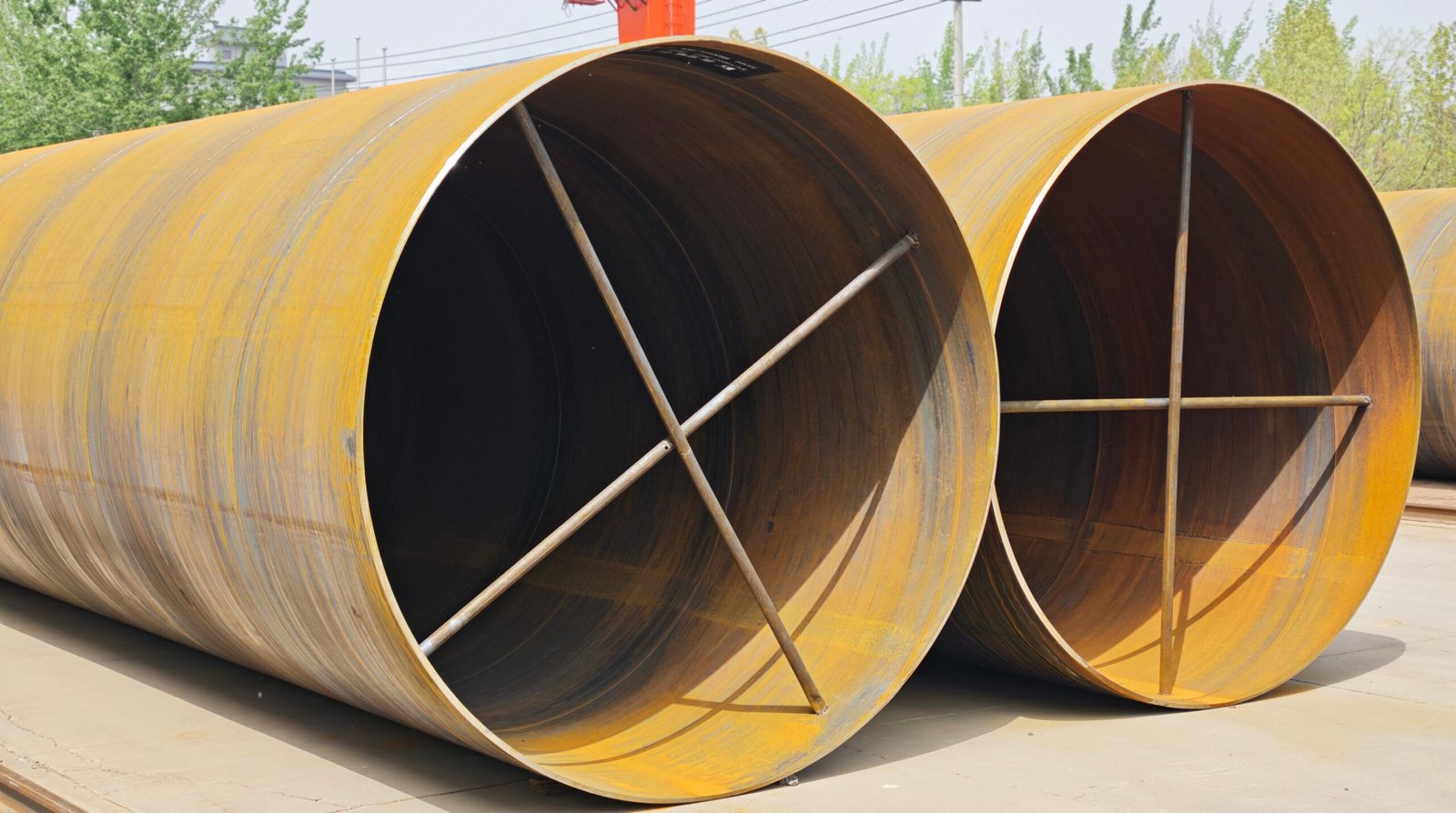
5. EN 10217-5: Submerged arc welded non-alloy and alloy steel tubes with high-temperature properties (SAW tubes)
· LSAW (Longitudinal submerged arc welding)
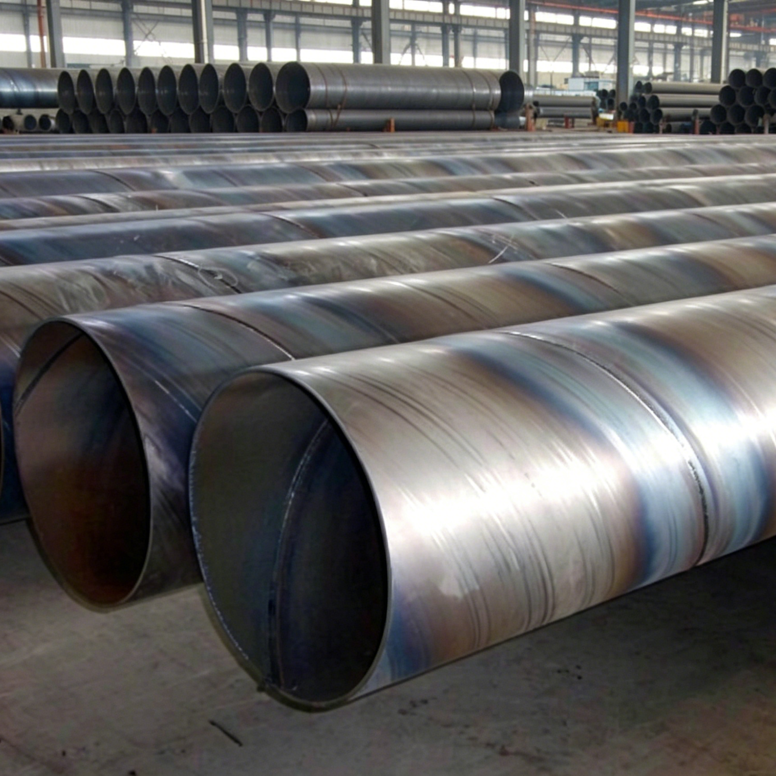
· SSAW (Spiral submerged arc welding)
6. EN 10217-6: Submerged arc welded non-alloy steel tubes with low-temperature properties
7. EN 10217-7: Stainless Steel
Mainly comprises two categories: austenitic and austenitic-ferritic stainless steel tubes.
Austenitic
Common grades:
· X2CrNi18-9
· X5CrNi18-10
· X6CrNiTi18-10
Austenitic-ferritic
· X2CrNiN23-4
· X2CrNiMoN22-5-3
| EN 10217-1 Chemical composition (cast analysis) a, in % by mass | |||||||||||||||
| Steel grade | C Max. | Si Max. | Mn Max. | P Max. | S Max. | Crb Max. | Mob Max. | Nib Max. | Altot Max. | Cub c Max. | Nbb Max. | Tib Max. | Vb Max. | Cr+Cu+Mo+Nib Max. | |
| Steel name | Steel number | ||||||||||||||
| P195TR1 | 1.0107 | 0,13 | 0,35 | 0,70 | 0,025 | 0,020 | 0,30 | 0,08 | 0,30 | – | 0,30 | 0,010 | 0,04 | 0,02 | 0,70 |
| P195TR2 | 1.0108 | 0,13 | 0,35 | 0,70 | 0,02b | ||||||||||
| P235TR1 | 1.0254 | 0,16 | 0,35 | 0,70 | – | ||||||||||
| P235TR2 | 1.0255 | 0,16 | 0,35 | 0,70 | 0,02b | ||||||||||
| P265TR1 | 1.0258 | 0,20 | 0,40 | 1,40 | – | ||||||||||
| P265TR1 | 1.0259 | 0,20 | 0,40 | 1,40 | 0,02b | ||||||||||
b Elements not included in this Table shall not be intentionally added to the steel without the agreement of the purchaser, except for elements which may be added for finishing the cast. All appropriate measures shall be taken to prevent the addition of undesirable elements from scrap or other materials used in the steel making process.
b The content of these elements need not be reported unless intentionally added to the cast.
c Option 3: In order to facilitate subsequent forming operation, an agreed maximum copper content lower than indicated and an agreed specified maximum tin content shall apply.
d This requirement is not applicable provided the steel contains a sufficient amount of other nitrogen binding elements, which shall be reported.
EN 10217-1
| Steel grades | Tensile properties | Impact properties | |||||||
| Steel Name | Steel Number | Upper yield strengthReH min forT mm | Tensile StrengthR m | ElongationA min.% c | Minimum averageabsorbed energyKV Jat a temperature of °CC | ||||
| T ≤16 | 16<T≤40 | l | t | l | t | ||||
| MPa * | 0 | -10 | 0 | ||||||
| P195TR1 | 1.0107 | 195 | 185 | 320-440 | 27 | 25 | – | – | – |
| P195TR2 | 1.0108 | 195 | 185 | 320-440 | 27 | 25 | 40 | 28d | 27 |
| P235TR1 | 1.0254 | 235 | 225 | 360-500 | 25 | 23 | – | – | – |
| P235TR2 | 1.0255 | 235 | 225 | 360-500 | 25 | 23 | 40 | 28d | 27 |
| P265TR1 | 1.0259 | 265 | 255 | 410-570 | 21 | 19 | – | – | – |
| P265TR2 | 1.0259 | 265 | 255 | 410-570 | 21 | 19 | 40 | 28d | 27 |
a For wall thickness greater than 40 mm the mechanical properties are subject to agreement.
c l = longitudinal; t = transverse.
d Option 5: Additionally, longitudinal impact strength shall be verified at – 10 °C.
* 1 MPa = 1 N/mm²
The dimensions specified in EN 10217 typically refer to the European standard for steel tubes, EN 10220.
| DN | NPS | OD (mm) | Sch 40 WT (mm) | Sch 80 WT (mm) |
| DN15 | 1/2″ | 21.3 | 2.77 | 3.73 |
| DN20 | 3/4″ | 26.9 | 2.87 | 3.91 |
| DN25 | 1″ | 33.4 | 3.38 | 4.55 |
| DN32 | 1-1/4″ | 42.2 | 3.56 | 4.85 |
| DN40 | 1-1/2″ | 48.3 | 3.68 | 5.08 |
| DN50 | 2″ | 60.3 | 3.91 | 5.54 |
| DN65 | 2-1/2″ | 76.1 | 5.16 | 7.01 |
| DN80 | 3″ | 88.9 | 5.49 | 7.62 |
| DN100 | 4″ | 114.3 | 6.02 | 8.56 |
| DN125 | 5″ | 141.3 | 6.55 | 9.53 |
| DN150 | 6″ | 168.3 | 7.11 | 10.97 |
| DN200 | 8″ | 219.1 | 8.18 | 12.70 |
| DN250 | 10″ | 273.0 | 9.27 | 15.09 |
| DN300 | 12″ | 323.9 | 9.53 | 17.48 |
| DN350 | 14″ | 355.6 | 9.53 | 19.05 |
| DN400 | 16″ | 406.4 | 9.53 | 21.44 |
| DN450 | 18″ | 457.0 | 9.53 | 23.83 |
| DN500 | 20″ | 508.0 | 9.53 | 26.19 |
| DN | NPS | OD (mm) | WT(mm) | |
| DN600 | 24″ | 610.0 | 8 – 25 | |
| DN700 | 28″ | 711.0 | 8 – 30 | |
| DN800 | 32″ | 813.0 | 10 – 32 | |
| DN900 | 36″ | 914.0 | 10 – 40 | |
| DN1000 | 40″ | 1016.0 | 12 – 40 | |
| DN1200 | 48″ | 1219.0 | 12 – 50 | |
EN 10217-1
| Outside diameter D | Outside Diameter (D) Tolerance | Wall Thickness (T) Tolerance | |
| T≤5 | 5<T ≤40 | ||
| D≤219,1 | ±1% or ±0,5 whichever is the greater | ±10 % or ±0,3 whichever is the greater | ±8 % or ±2 whichever is the smaller |
| D > 219,1 | ±0,75 % or ±6 whichever is the smaller | ||
Maximum height of the weld seam for EW and BW tubes(dimensions in mm)
| Manufacturing Process | Quality TR1 | Quality TR2 | ||
| Outside | Inside | Outside | Outside | |
| EW | Trimmed | 1,5 | Trimmed | 0,5 + 0,05T |
| BW | As rolled | 0,5 + 0,05T | – | – |
Maximum height of the weld seam for SAW tubes(dimensions in mm)
| Wall thickness T | Maximum height of the weld seam | |
| Outside | Inside | |
| T ≤ 12,5 | 3,5 | 3,5 |
| T > 12,5 | 4,8 | 4,8 |
| Dimensions in mm | ||
| Length | Tolerances on exact length for outside diameter (D) | |
| L | < 406,4≥406,4 | |
| L≤ 6000 | +10 0 | +25 0 |
| 6000 < L ≤ 12000 | +15 0 | +50 0 |
| L > 12000 | + by agreement 0 | |
The tolerance for ovality is generally required to be ≤ 2% of the outer diameter (OD).
Calculation formula:
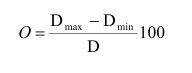
O :out-of-roundness
D : specified outside diameter in % in mm
D max, D min. = maximum and minimum outside diameter measured in the same plane in mm
Energy Industry (Oil & Gas / Power): Oil and gas pipelines、Gathering systems、Steam pipelines、Boiler piping.
EN 10217-2 (P235GH / P265GH)
Pressure Equipment: Pressure vessels、Storage tanks、Heat exchangers.
Industrial Piping Systems:、Petrochemical industry、Chemical plants、Process Piping.
Infrastructure: Water Supply Systems、Gas Distribution、Firefighting Pipelines.
Special Service: LNG Projects、Pipelines in Cold Regions.
Fill in the form below and our team will be happy to assist you


