



Introduction
Natural gas pipe sizing determines the required pipe diameter based on flow rate, operating pressure, pipe length, and allowable pressure drop. Because these factors interact, flow rate alone is not enough to determine pipe size. This guide covers the main sizing factors and calculation steps.
What Factors Affect Natural Gas Pipe Size?
| Factor | Effect on Pipe Sizing |
| Gas flow rate | Higher flow rates generally require larger pipe diameters. |
| Operating pressure | Affects gas density and the available pressure for flow. |
| Pipe length | Longer pipes generally result in greater pressure loss. |
| Allowable pressure drop | Defines the maximum pressure loss the system can tolerate. |
| Pipe material and roughness | Affect friction and pressure loss along the pipe. |
| Fittings and valves | Add additional pressure loss to the piping system. |
How to Calculate Natural Gas Pipe Size?
Natural gas pipe sizing can be simplified into four basic steps:
| Step | Key Parameter | What to Determine |
| 1 | Gas flow rate | Required gas flow in CFH, SCFH, or m³/h |
| 2 | Operating pressure | Available inlet pressure and required outlet pressure |
| 3 | Pipe length & pressure drop | Pipe run length and allowable pressure loss |
| 4 | Pipe diameter | Required diameter based on the above parameters |
Basic Sizing Process
- Higher flow rate→ generally requires a larger pipe.
- Longer pipe length→ generally results in greater pressure loss.
- Lower allowable pressure drop→ may require a larger pipe.
- Higher operating pressure→ can affect the required pipe size for a given flow rate.
The final pipe diameter should be selected using an applicable natural gas pipe sizing chart, calculation method, or engineering software, and checked against the relevant codes and project requirements.
Basic Natural Gas Pipe Sizing Formula
Natural gas pipe sizing is based on the relationship between gas flow, pipe diameter, pressure, pipe length, and pressure drop. A basic pressure-loss relationship can be expressed using the Darcy–Weisbach equation:
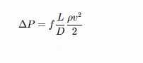
- ΔP = Frictional pressure loss
- f = Darcy friction factor (dimensionless)
- L = Pipe length
- D = Internal pipe diameter
- ρ = Natural gas density
- v = Average gas velocity
For natural gas systems, more specific gas-flow equations such as the Weymouth or Panhandle equations may be used, particularly for pipeline applications. The appropriate equation depends on the operating pressure, pipe length, gas properties, and applicable engineering standard.
Therefore, the formula should be used together with the relevant sizing method rather than as a standalone pipe-size selection rule.
Natural Gas Pipe Sizing Reference Table
Natural gas pipe size is selected based on flow rate, operating pressure, pipe length, allowable pressure drop, and other system conditions. Therefore, a pipe diameter cannot be assigned to a specific flow range without defined design conditions.
The table below provides a general reference for common nominal pipe sizes and outside diameters.
| Nominal Pipe Size | Approx. Outside Diameter |
| 1″ | 33.4 mm |
| 1½” | 48.3 mm |
| 2″ | 60.3 mm |
| 3″ | 88.9 mm |
| 4″ | 114.3 mm |
| 6″ | 168.3 mm |
| 8″ | 219.1 mm |
Note: Nominal pipe size alone does not determine natural gas flow capacity. Actual flow capacity varies with operating pressure, pipe length, allowable pressure drop, gas properties, pipe roughness, and the applicable sizing method.
Common Natural Gas Pipe Sizes
Natural gas pipes are commonly specified using NPS (Nominal Pipe Size) or DN (Nominal Diameter). Outside diameter and wall thickness are separate dimensions used to define the actual pipe specification.
| Dimension | Example |
| NPS | 1″, 2″, 4″, 6″ |
| DN | DN25, DN50, DN100, DN150 |
| Outside Diameter (OD) | Actual pipe outside diameter |
| Wall Thickness (WT) | Varies by pipe specification and pressure requirements |
Pipe diameter and wall thickness serve different purposes: diameter primarily affects flow capacity and pressure loss, while wall thickness relates to pressure containment and mechanical strength.
Pipe Diameter vs. Wall Thickness
| Parameter | Main Function |
| Pipe diameter | Affects flow capacity and pressure loss |
| Wall thickness | Affects pressure containment and mechanical strength |
Therefore, pipe sizing determines the required diameter, while wall thickness is selected based on pressure, material strength, design requirements, and applicable standards.
NPS vs. DN for Natural Gas Pipe Sizing
Natural gas steel pipes may be specified using NPS (Nominal Pipe Size) or DN (Nominal Diameter), depending on the applicable standard and project requirements.
NPS is commonly used in ASME and ASTM-based piping systems, while DN is widely used in international and metric-based specifications. NPS and DN are nominal designations and should not be treated as the exact outside diameter of the pipe.
Choosing Steel Pipe for Natural Gas Applications
After determining the required pipe diameter, the steel pipe should be selected based on pressure, application, pipe size, wall thickness, and applicable standards. Different manufacturing processes are suitable for different natural gas piping requirements.
| Steel Pipe Type | Typical Application |
| ERW Steel Pipe | Gas distribution and general piping applications |
| Seamless Steel Pipe | Applications where seamless construction is specified |
| LSAW Steel Pipe | Large-diameter natural gas transmission pipelines |
For pipeline projects, API 5L is a commonly specified standard for line pipe. The required pipe grade, PSL level, diameter, and wall thickness should be determined according to the project design and applicable specifications.
FAQ
How do I calculate natural gas pipe size?
Determine the required gas flow rate, operating pressure, pipe length, and allowable pressure drop. Then use an applicable natural gas pipe sizing chart, calculation method, or engineering software to select the appropriate pipe diameter.
What size pipe is needed for natural gas?
There is no single pipe size suitable for every natural gas system. The required diameter depends on gas flow rate, operating pressure, pipe length, allowable pressure drop, and applicable codes or project requirements.
Does a larger natural gas pipe reduce pressure drop?
Generally, yes. A larger pipe diameter reduces flow resistance and can lower pressure loss for a given flow rate and pipe length. However, the pipe should be sized according to the actual system requirements rather than simply choosing the largest available diameter.