


Engineering Challenges in Heavy Crude Oil Pipeline Construction
Heavy crude oil presents specific transportation challenges due to its high viscosity, temperature sensitivity, and potentially corrosive composition. These properties affect pipeline hydraulics, operating conditions, and material selection.
High Viscosity and Increased Flow Resistance
Heavy crude oil has higher viscosity than conventional crude oil, resulting in greater friction losses during pipeline transportation. Maintaining the required flow rate may therefore require higher pumping pressure, increased energy consumption, or additional pumping capacity. Pipeline diameter, transportation distance, and target flow rate must be considered during hydraulic design.
Temperature-Dependent Flow Performance
Heavy crude oil viscosity generally increases as temperature decreases, making transportation more difficult in cold environments and during pipeline shutdowns. Depending on the crude oil properties and operating requirements, heating systems or other viscosity-reduction measures may be necessary to maintain stable flow and avoid excessive pressure losses.
Corrosion and Flow Assurance Risks
Water, sulfur compounds, organic acids, and other constituents in heavy crude oil can contribute to internal corrosion. Water and sediment accumulation may also create localized corrosion risks and affect flow stability. Material selection, internal corrosion assessment, and appropriate monitoring measures should therefore be based on the actual crude oil composition and operating conditions.
Transportation and Pipeline Design Considerations for Heavy Crude Oil
Heavy crude oil pipeline design focuses on maintaining the required flow rate while controlling pressure loss, operating temperature, and pumping energy. Three factors are particularly important:
1. Temperature and Viscosity Control
Heavy crude oil transportation often requires viscosity reduction to maintain flowability and limit pumping resistance. Three common approaches are used:
- Heating:Raises crude oil temperature to reduce viscosity.
- Thermal Insulation:Reduces heat loss and helps maintain the required operating temperature.
- Diluent Blending:Mixes lighter hydrocarbons with heavy crude to improve flow characteristics.
The selection depends on crude oil properties, transportation distance, energy consumption, and operating costs.
2. Pipeline Diameter and Pressure Loss
Pipeline diameter is determined through hydraulic calculations rather than a fixed size range. A preliminary internal diameter can be estimated from the required flow rate and design velocity:
Di = √(4Q / πv)
Where:
- Di = Internal diameter (m)
- Q = Flow rate (m³/s)
- v = Average flow velocity (m/s)
After selecting a preliminary diameter, engineers calculate frictional pressure loss using the Darcy–Weisbach equation:
ΔP = f × (L / Di) × (ρv² / 2)
Where:
- ΔP = Pressure loss (Pa)
- f = Darcy friction factor
- L = Pipeline length (m)
- Di = Internal diameter (m)
- ρ = Crude oil density (kg/m³)
- v = Average flow velocity (m/s)
The results help determine whether the proposed pipe size can meet the required transportation capacity and pressure limits.
3. Pumping Stations and Operating Pressure
Pumping stations provide the energy required to overcome pipeline resistance and maintain the target flow rate. Their configuration depends on the total pressure loss and the allowable operating pressure.
For long-distance pipelines, additional pumping stations may be installed when the pressure available at the pipeline outlet of one station is insufficient to maintain the required flow.
Pump shaft power can be estimated using:
Ps = (ρ × g × Q × H) / (1000 × η)
Where Ps is pump shaft power (kW), ρ is crude oil density (kg/m³), g is gravitational acceleration (9.81 m/s²), Q is flow rate (m³/s), H is required pump head (m), and η is pump efficiency.
Pump capacity and station spacing should be determined from the pipeline hydraulic profile. Operating pressure must remain within the maximum allowable operating pressure (MAOP), with suitable pressure monitoring and protection systems.
Steel Pipe Selection for Heavy Crude Oil Pipeline Projects
The choice of steel pipe affects pipeline strength, fabrication, field installation, and long-term performance. Rather than selecting a pipe solely by manufacturing process or nominal dimensions, project engineers should evaluate the complete combination of material grade, pipe geometry, weld quality, and corrosion protection.
API 5L Grades and Material Requirements
API 5L line pipe grades commonly used in crude oil transmission projects include X42, X52, X60, X65, and X70. The number following “X” represents the specified minimum yield strength in ksi.
| API 5L Grade | Minimum Yield Strength |
| X42 | 42,000 psi (290 MPa) |
| X52 | 52,000 psi (360 MPa) |
| X60 | 60,000 psi (415 MPa) |
| X65 | 65,000 psi (448 MPa) |
| X70 | 70,000 psi (483 MPa) |
Steel Grade Selection for Heavy Crude Oil Pipelines
- X42–X52:Suitable for pipeline projects with relatively moderate strength requirements.
- X60–X65:Used in higher-pressure transmission systems where greater yield strength is required.
- X70:Applied in high-strength pipeline designs to support demanding pressure and structural requirements.
Higher-grade steel can help optimize pipe wall thickness under certain design conditions. However, grade selection must also consider fracture toughness, weldability, fabrication requirements, and the applicable pipeline design code.
API 5L PSL2 may be specified when projects require additional controls on chemical composition, mechanical properties, and testing compared with PSL1. The final grade and PSL level should be defined in the project material specification.
LSAW and SSAW Pipe Selection
Large-diameter welded pipes are commonly considered for main transmission pipeline sections.
LSAW Steel Pipe
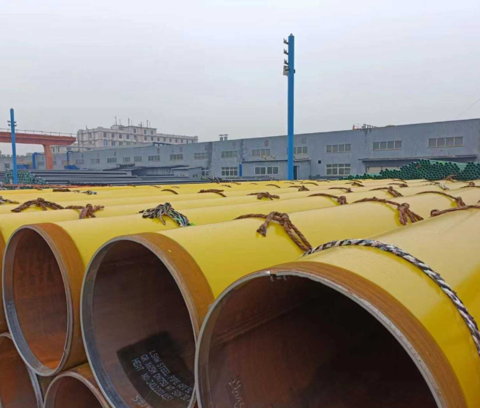
Longitudinal submerged arc welded pipe is manufactured from formed steel plate with a longitudinal weld seam. It is suitable for projects requiring large diameters, substantial wall thicknesses, and strict dimensional control. Its plate-based forming process also allows manufacturers to produce pipes according to specific project dimensions.
SSAW Steel Pipe
Spiral submerged arc welded pipe is formed from steel coil, with the weld seam following a helical path. The process provides flexibility in producing large-diameter pipes and can be considered for long-distance transmission systems when permitted by the project specification and design requirements.
The selection between LSAW and SSAW should consider the applicable pipeline code, design pressure, pipe dimensions, material requirements, weld inspection criteria, and project approval requirements.
Wall Thickness and Mechanical Performance
Wall thickness affects the pressure-bearing capacity, structural strength, and installation performance of steel pipes used in heavy crude oil pipeline construction.
Typical manufacturing ranges for large-diameter pipeline pipes include:
| Pipe Type | Outside Diameter | Wall Thickness | Typical Length |
| LSAW | 406–1524 mm | 6–60 mm | 6–12.5 m |
| SSAW | 219–3500 mm | 5–25 mm | 6–12 m |
For heavy crude oil transmission projects, pipe wall thickness and dimensional tolerances should be specified according to the project design and applicable API 5L requirements.
Key inspection items include outside diameter, wall thickness, pipe-end dimensions, ovality, and straightness. These checks help ensure consistent pipe dimensions and reliable fit-up during field welding.
Pipe length should also be coordinated with transportation restrictions, site handling equipment, and field jointing requirements.
External Corrosion Protection and Internal Corrosion Assessment
In heavy crude oil pipeline construction, corrosion protection must be addressed from pipe delivery through installation and commissioning.
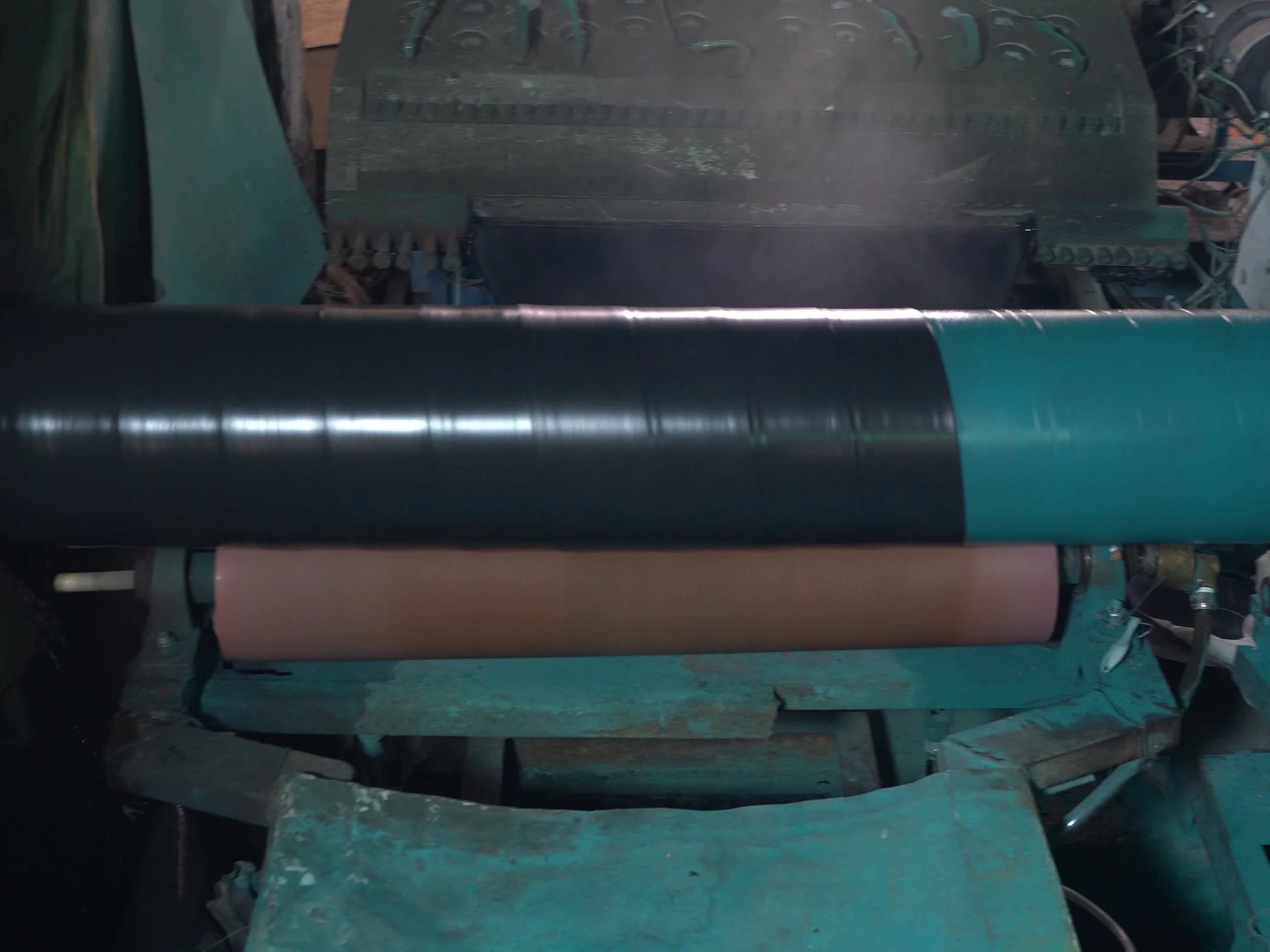
For buried pipeline sections, external coatings must withstand handling, lifting, lowering-in, and backfilling. Any coating damage should be identified and repaired before the pipe is buried. Field-joint coating is also essential to maintain continuous corrosion protection across welded connections.
Internal corrosion requires separate assessment. Heavy crude oil may contain water, sediment, salts, CO₂, and H₂S, which can contribute to corrosion inside the pipeline. Water and sediment accumulation at low points may further increase localized corrosion risks.
Crude oil composition and water content should therefore be evaluated when determining internal corrosion protection and inspection requirements.