

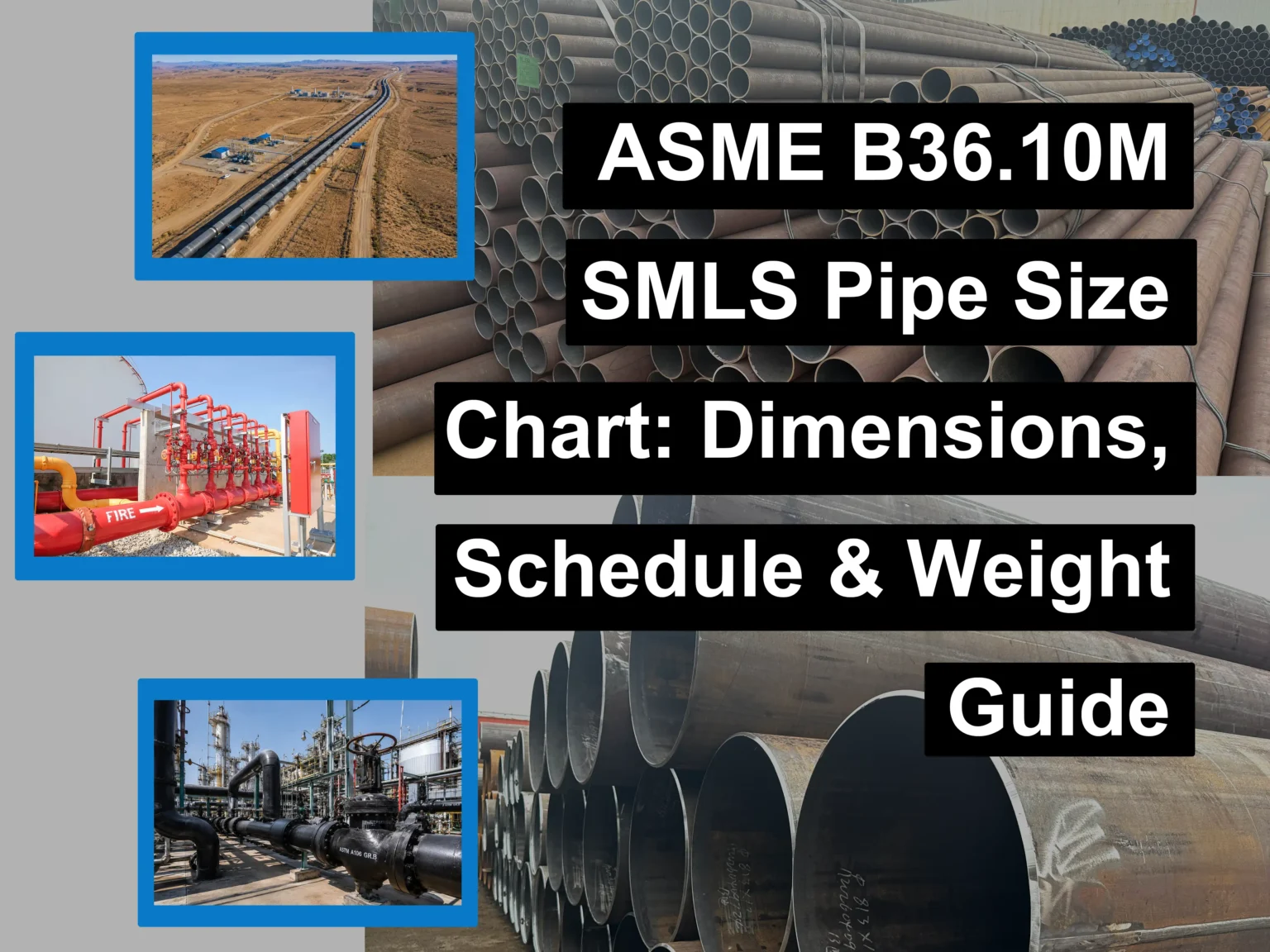
ASME B36.10M is one of the most fundamental dimensional standards for seamless (SMLS) and welded steel pipes made of carbon and alloy steels. It primarily specifies NPS (Nominal Pipe Size), OD (Outside Diameter), Wall Thickness, Schedule (SCH), and Weight.
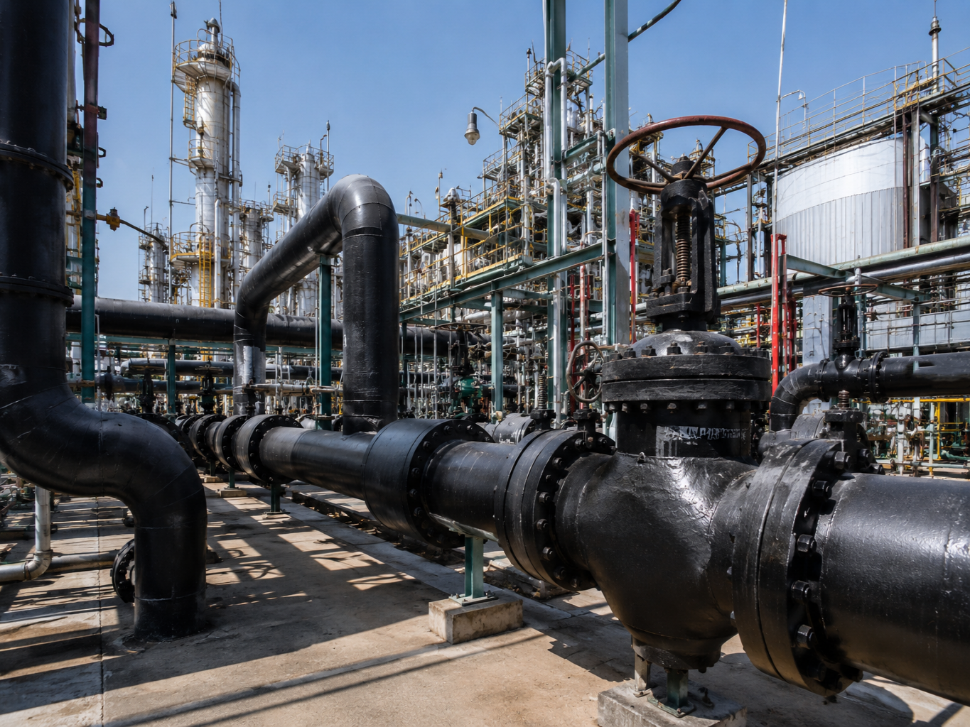
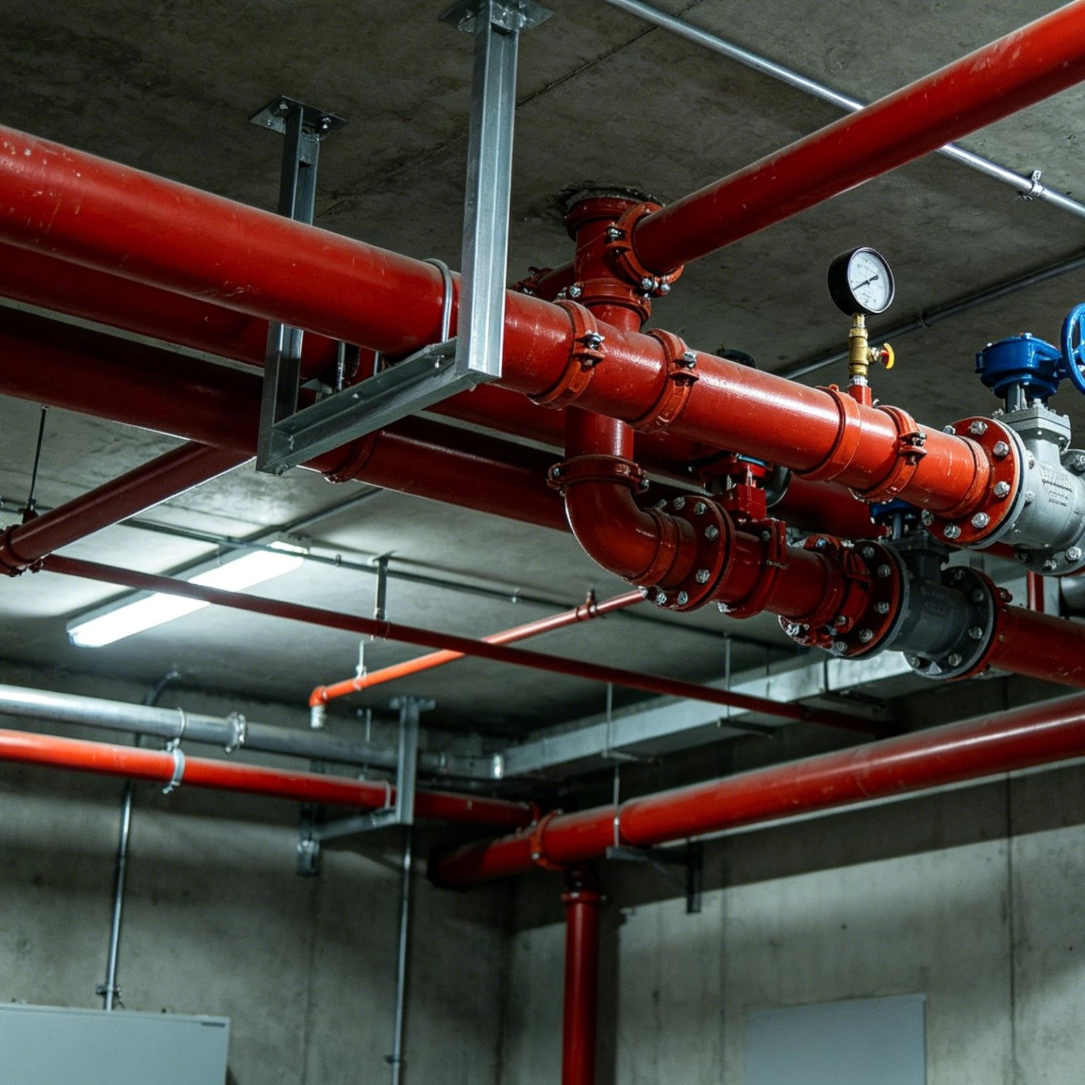
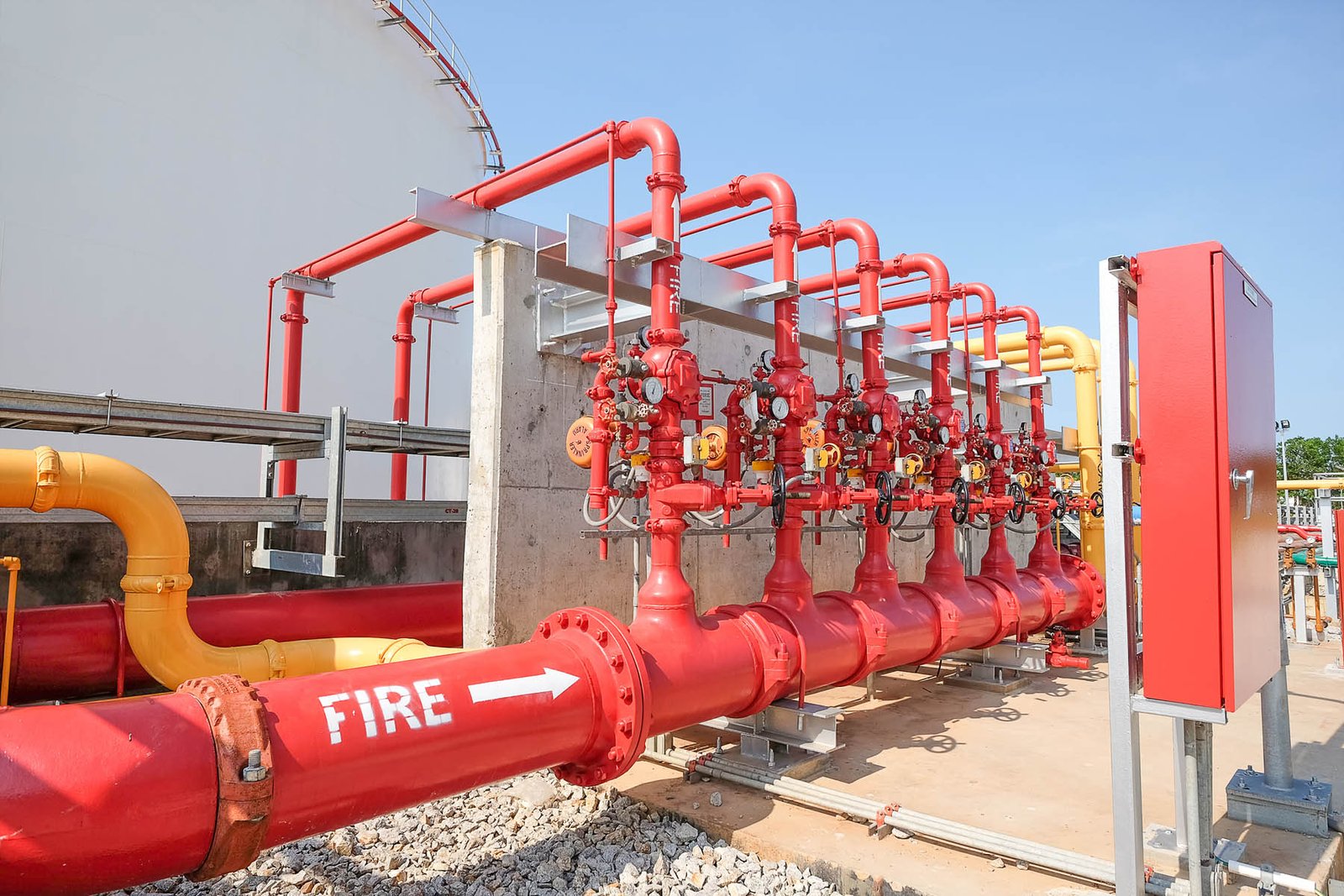
It is one of the most widely used pipe sizing standards in global industrial piping systems, with extensive applications in industrial and mechanical sectors such as Oil & Gas Pipelines, Pressure Piping Systems, Refinery Projects, Boiler Systems, and Fire Protection Pipelines.
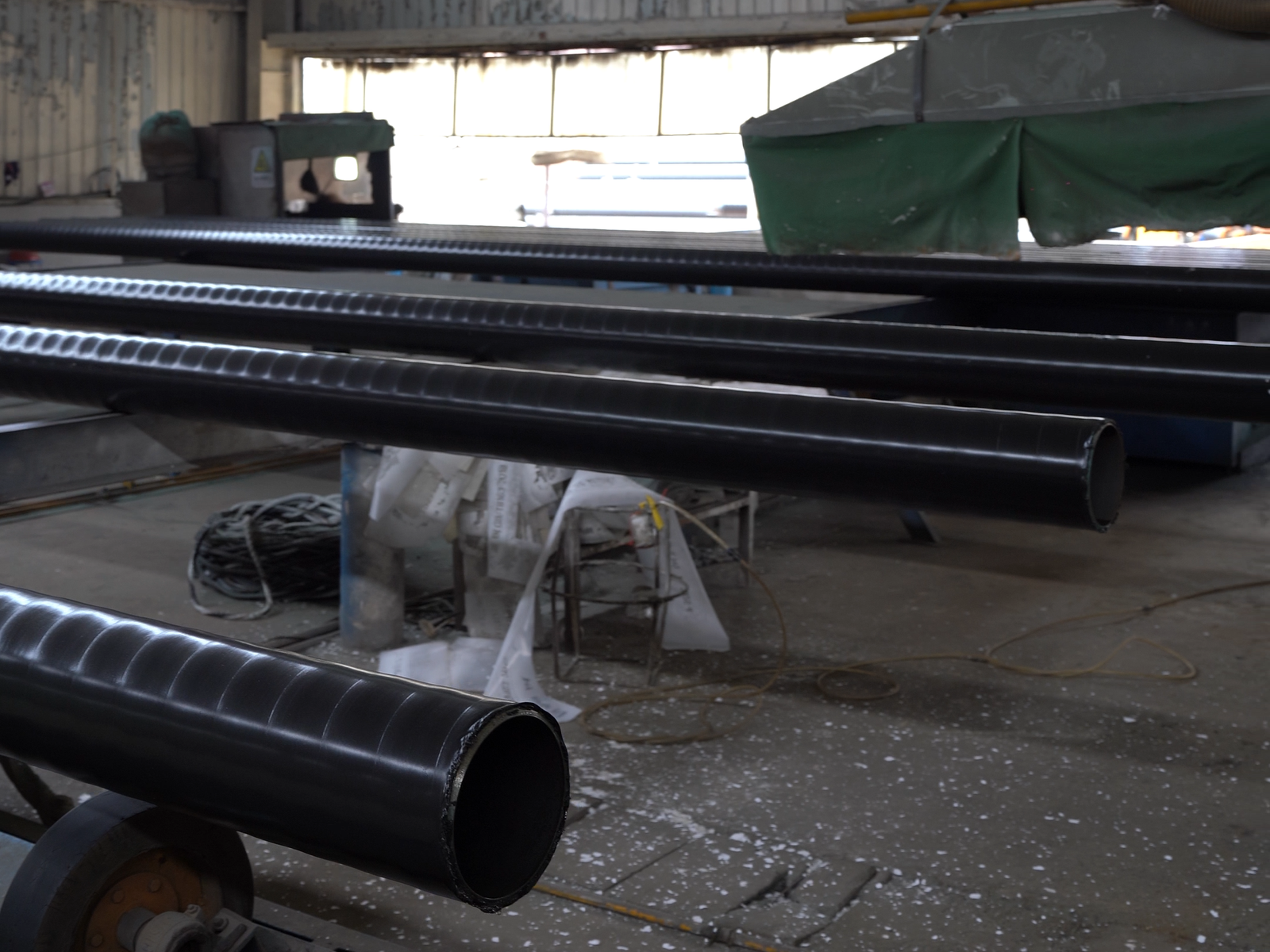
Due to its seamless construction, SMLS (Seamless Steel Line Pipe) is typically suitable for:
- High-pressure service
- High-temperature conditions
- Corrosive environments
- Critical pipeline systems
Compared to ERW (Electric Resistance Welded) pipe, it is better suited for high-risk industrial applications.
This article will provide a comprehensive overview of ASME B36.10M SMLS pipe sizing from a practical procurement and selection perspective.
ASME B36.10M SMLS Pipe Size Chart
In the ASME B36.10M standard, for a given NPS size, the outer diameter of the pipe remains constant, while the wall thickness varies depending on the pipe number.
In the ASME B36.10M system, pipe sizes are not defined by their actual inner diameters; instead, NPS (Nominal Pipe Size) is used as a standardized naming convention. For the same NPS size, the outside diameter (OD) remains constant regardless of wall thickness, while the inside diameter (ID) decreases as the wall thickness increases.
For example:
The outside diameter of an NPS 6 pipe is always 168.3 mm. Whether it is SCH 40, SCH 80, or SCH 160, the only thing that changes is the wall thickness.
| DN | NPS | Outside Diameter (mm) | SCH 10 WT (mm) | SCH 40 WT (mm) | SCH 80 WT (mm) | SCH 160 WT (mm) | SCH 40 Weight (kg/m) | SCH 80 Weight (kg/m) |
| DN6 | 1/8″ | 10.3 | 1.24 | 1.73 | 2.41 | 3.20 | 0.37 | 0.48 |
| DN8 | 1/4″ | 13.7 | 1.65 | 2.24 | 3.02 | 4.78 | 0.63 | 0.80 |
| DN10 | 3/8″ | 17.1 | 1.65 | 2.31 | 3.20 | 4.78 | 0.86 | 1.14 |
| DN15 | 1/2″ | 21.3 | 2.11 | 2.77 | 3.73 | 4.78 | 1.27 | 1.62 |
| DN20 | 3/4″ | 26.7 | 2.11 | 2.87 | 3.91 | 5.56 | 1.69 | 2.20 |
| DN25 | 1″ | 33.4 | 2.77 | 3.38 | 4.55 | 6.35 | 2.50 | 3.24 |
| DN32 | 1-1/4″ | 42.2 | 2.77 | 3.56 | 4.85 | 6.35 | 3.39 | 4.47 |
| DN40 | 1-1/2″ | 48.3 | 2.77 | 3.68 | 5.08 | 7.14 | 4.05 | 5.41 |
| DN50 | 2″ | 60.3 | 2.77 | 3.91 | 5.54 | 8.74 | 5.44 | 7.48 |
| DN65 | 2-1/2″ | 73.0 | 3.05 | 5.16 | 7.01 | 9.53 | 8.63 | 11.41 |
| DN80 | 3″ | 88.9 | 3.05 | 5.49 | 7.62 | 11.13 | 11.29 | 15.27 |
| DN90 | 3-1/2″ | 101.6 | 3.05 | 5.74 | 8.08 | 12.70 | 13.57 | 18.63 |
| DN100 | 4″ | 114.3 | 3.05 | 6.02 | 8.56 | 13.49 | 16.07 | 22.32 |
| DN125 | 5″ | 141.3 | 3.40 | 6.55 | 9.53 | 15.88 | 21.77 | 31.26 |
| DN150 | 6″ | 168.3 | 3.40 | 7.11 | 10.97 | 18.26 | 28.26 | 42.56 |
| DN200 | 8″ | 219.1 | 3.76 | 8.18 | 12.70 | 23.01 | 42.55 | 64.64 |
| DN250 | 10″ | 273.1 | 4.19 | 9.27 | 15.09 | 28.58 | 60.32 | 95.52 |
| DN300 | 12″ | 323.9 | 4.57 | 10.31 | 17.48 | 33.32 | 79.72 | 129.67 |
| DN350 | 14″ | 355.6 | 4.78 | 11.13 | 19.05 | 35.71 | 94.55 | 159.34 |
| DN400 | 16″ | 406.4 | 4.78 | 12.70 | 21.44 | 40.49 | 124.69 | 205.31 |
| DN450 | 18″ | 457.0 | 4.78 | 14.27 | 23.83 | 46.02 | 155.81 | 254.31 |
| DN500 | 20″ | 508.0 | 5.54 | 15.09 | 26.19 | 50.01 | 183.65 | 317.55 |
| DN600 | 24″ | 609.6 | 6.35 | 17.48 | 30.96 | 59.54 | 255.73 | 441.62 |
ASME B36.10M Pipe Size Tolerances
OD Tolerance for Seamless Pipes
NPS 1/8 to NPS 10: ±1/64 inch (±0.4 mm).
NPS 12 and above: ±1% of the nominal diameter.
Inside Diameter (ID) Tolerance
Not typically specified; inferred from the OD and wall thickness tolerances.
For a specific ID tolerance, control the OD and wall thickness within the prescribed tolerances.
Wall Thickness Tolerance
Generally ±12.5% of the nominal wall thickness for most pipe sizes and schedules as per ASME B36.10M and B36.19M.
The actual wall thickness of steel pipes must not be less than 87.5% of the nominal wall thickness.
Weight Tolerance
Generally accepted weight tolerances for pipes are:
| Pipe Type | Typical Weight Tolerance |
| Seamless Steel Pipe (SMLS) | ±10% of theoretical weight |
| Welded Steel Pipe | ±5% to ±10% |
| API Line Pipe | According to API specification |
| Heavy Wall Pipe | Usually tighter control required |
Standard Pipe Lengths and Tolerances
| Length Type | Typical Tolerance |
| Fixed Length Pipe | Pipe length is manufactured according to the specified purchase order requirement. Typical tolerance is approximately +0 to +1/4” to +1/2” (+6 mm to +12 mm), depending on the total pipe length. |
| Random Length Pipe | Single random length generally ranges from 16 to 22 ft (4.9–6.7 m), while double random length typically ranges from 35 to 45 ft (10.7–13.7 m). Specific tolerances are usually determined by manufacturer standards or project agreements. |
| Cut Length Pipe | Produced according to exact project dimensions. Length tolerances are generally similar to fixed-length pipe, with final allowable deviation defined in project specifications or contractual documents. |
What Is ASME B36.10M?
ASME B36.10M is a dimensional standard for “Welded and Seamless Wrought Steel Pipe.” This standard primarily applies to carbon steel pipe and alloy steel pipe. Its core provisions include:
- Pipe Outside Diameter
- Wall Thickness
- Schedule Number
- Dimensional Standardization
ASME B36.10M is essentially a dimensional standard; it does not specify the chemical composition or mechanical properties of steel pipes, which are typically defined by material standards such as ASTM, API, and ISO.
Therefore, in actual industrial projects, ASME B36.10M is often used in conjunction with material standards such as ASTM A106, ASTM A53, and API 5L to form a comprehensive system of industrial steel pipe specifications.
Relationship Between ASME B36.10M and Pipe Material Standards
In the industrial steel pipe system, ASME B36.10M and material standards such as ASTM, API, and ISO are not interchangeable; rather, they form a complementary relationship between “dimensional standards” and “material standards.”
| Standard Type | Standard | Main Function | Typical Applications |
| Dimension Standard | ASME B36.10M | Defines OD, WT, SCH & dimensions | Industrial Pipe Sizing |
| Material Standard | ASTM A106 | High-temperature seamless carbon steel pipe | Boiler & Steam Systems |
| Material Standard | ASTM A53 | General-purpose carbon steel pipe | Water, Fire Protection |
| Material Standard | API 5L | Line pipe for oil & gas transportation | Oil & Gas Pipelines |
| Material Standard | ASTM A333 | Low-temperature carbon steel pipe | Cryogenic Service |
| Material Standard | ASTM A335 | Alloy steel pipe for high temperature | Power Plant & Refinery |
| International Standard | ISO Standards | International material/specification system | Global Industrial Projects |
Key Terms in ASME B36.10M
| Term | Meaning |
| NPS | Nominal Pipe Size |
| DN | Diameter Nominal |
| OD | Outside Diameter |
| ID | Inside Diameter |
| SCH | Pipe Schedule |
| WT | Wall Thickness |
| STD | Standard Weight |
| XS | Extra Strong |
| XXS | Double Extra Strong |
Common Pipe Schedules in ASME B36.10M
In industrial piping systems, the selection of pipe schedule essentially involves striking a balance between: pressure capacity, service life, and project cost.
For HVAC or low-pressure water systems, SCH 10 is sufficient to meet operational requirements while also reducing:
- pipe weight
- welding costs
- installation difficulty
SCH 40 is the most common pipe schedule used in industrial projects worldwide and serves as the default specification in many standard industrial systems. Compared to SCH 10, SCH 40 features greater wall thickness and mechanical strength, thereby offering an optimal balance between pressure-bearing capacity, manufacturing costs, and ease of installation.
SCH 40 is widely used in: water transmission systems, fire protection pipelines, mechanical piping, and utility piping.
For example, in commercial fire protection systems, SCH 40 ASTM A53 Grade B typically meets the system’s operating pressure requirements while effectively reducing material costs, installation complexity, and threading workload.
As a result, SCH 40 is one of the industrial steel pipe specifications with the most established inventory and the most stable supply worldwide.
However, in refineries, steam systems, or oil and gas pipeline systems, higher operating pressures and corrosion risks often necessitate the use of SCH 80 or even SCH 160.
As wall thickness increases, steel pipes can not only withstand higher internal pressures but also provide a greater corrosion allowance, thereby extending the system’s service life.
However, thicker pipe walls also mean:
- Higher material costs
- More difficult welding
- Increased shipping weight
In actual engineering projects, there is no absolute rule that “thicker is better” when selecting pipe schedules; rather, a comprehensive balance must be struck based on design conditions.
How to Choose ASME B36.10M Pipe Sizes for Different Applications
How to Choose ASME B36.10M Pipe Size for Main Steam Line
In high-pressure steam piping systems, the ASME B36.10M sizing system is typically used in conjunction with ASTM A106 seamless steel pipe.
In the steam systems of power plants and refineries, high-pressure steam piping typically refers to the main steam line (MSL), which transports superheated steam directly from the boiler outlet to the turbine inlet.
Main steam lines are responsible for transporting large volumes of steam throughout the system. If the pipe diameter is too small, it can result in excessively high steam velocities, significantly increasing pressure loss and flow turbulence. In actual industrial projects, main steam lines typically use larger pipe sizes, while branch steam lines use appropriately smaller diameters.
In power plant or refinery steam systems:
- Main steam headers are commonly NPS 8–24 (DN200–DN600)
- Process steam branches are typically NPS 1–6 (DN25–DN150)
Since these systems operate continuously under high-temperature and high-pressure conditions, steel pipes must not only withstand internal steam pressure but also cope with thermal stress caused by continuous thermal expansion.
As operating temperatures rise, the allowable stress of the steel gradually decreases; therefore, engineers typically increase the pipe schedule to enhance wall thickness and improve the system’s safety margin. This is a key reason why SCH 80 is generally more common than SCH 40 in high-pressure steam systems.
ALLLAND Steel Pipe possesses extensive manufacturing expertise in seamless steel pipe production and offers high-temperature, high-pressure steel pipe solutions compliant with standards such as ASTM A106 and ASME B36.10M, suitable for industrial applications including boiler systems, power plants, and refinery steam projects.
How to Select Pipe Sizes for Refinery Process Piping Systems
In refinery process piping systems, the selection of pipe sizes is typically more complex than in ordinary industrial piping. Refinery facilities are not only subject to operating conditions such as:
- High temperatures
- Corrosive media
- Pressure fluctuations
- Continuous operation
but must also withstand the long-term effects of frequent thermal expansion and pressure cycling. As a result, refinery piping systems generally adopt a more conservative approach to sizing, wall thickness, and material selection.
For example:
- Small process branch lines typically use NPS 1–4 (DN25–DN100)
- Main process piping commonly uses NPS 6–12 (DN150–DN300)
- Large transfer lines may reach NPS 16–24 (DN400–DN600)
The wall thickness of steel pipes gradually decreases over time. Therefore, engineers typically do not select wall thickness based solely on the theoretical design pressure; instead, they add a corrosion allowance to compensate for long-term corrosion loss.
Choosing ASME B36.10M Pipe Size for Fire Protection Systems
Because fire suppression systems must deliver a steady flow of water quickly during emergencies, pipe diameter design not only affects water delivery capacity but also directly impacts the fire-extinguishing efficiency of the entire sprinkler system.
DN25–DN100 is typically used for sprinkler branch lines, as smaller pipe diameters make it easier to control sprinkler flow distribution while reducing system installation costs. Meanwhile, DN150–DN250 is better suited for fire main piping to ensure a high water supply capacity during fire emergencies.
ALLLAND Steel Pipe offers fire sprinkler pipe products that comply with standards such as ASTM A53 and ASTM A795. We also support a wide range of fire protection system fabrication needs, including galvanized steel pipe, grooved pipe, and threaded pipe, to better meet the application requirements of commercial building and industrial fire protection projects.
- DN25–DN32 are commonly used for individual sprinkler branches
- DN40–DN65 are commonly used for zone sprinkler distribution lines
- DN80–DN100 are more commonly used for floor-level fire piping
This “small branch” design effectively controls water velocity and maintains system pressure balance,
thereby ensuring that all sprinkler heads receive a uniform water supply during a fire.
Pipe Size Selection in Oil & Gas Transmission Pipelines
Oil and gas pipelines often need to transport large volumes of fluid over long distances; in large-scale oil and gas pipeline projects, trunk lines typically use larger pipe sizes.
Trunk lines typically use pipe sizes ranging from DN600 to DN1200 (NPS 24–48) or even larger, whereas gathering lines generally use smaller diameters, such as DN50 to DN300 (NPS 2–12).
In terms of material selection, the American Petroleum Institute (API) 5L is one of the most fundamental line pipe standards for oil and gas transmission pipelines.
When pipe sizes exceed DN600 (NPS 24), industrial projects typically begin to widely adopt:
- LSAW pipe
- DSAW pipe
- SSAW pipe
rather than seamless pipe. This is because as pipe diameter increases, the difficulty of manufacturing seamless pipe rises sharply.
In modern oil and gas transmission engineering, SMLS pipe is still widely used in medium- and small-diameter high-pressure systems, while LSAW pipe is gradually becoming the dominant choice for large-diameter long-distance pipelines.
In large-scale oil and gas pipeline projects, whether steel pipe manufacturers possess stable large-diameter forming capabilities, automated welding processes, and experience with API 5L projects often directly impacts pipeline welding quality and the reliability of long-distance transportation.
ASME B36.10M vs ASME B36.19M
| Item | ASME B36.10M | ASME B36.19M |
| Main Material | Carbon Steel | Stainless Steel |
| Typical Application | Industrial Pressure Pipe | Stainless Process Pipe |
| Common Schedules | SCH 40 / 80 / 160 | SCH 10S / 40S |
| Corrosion Resistance | Depends on material | Higher |
*Due to the different material properties of stainless steel:
Many wall thickness specifications in B36.19M are not entirely consistent with those in B36.10M.
In particular, SCH 10S and SCH 40S are more common specifications for stainless steel pipes.
FAQ
STD means “Standard Weight,” a traditional pipe wall thickness classification in ASME B36.10M. In many pipe sizes, STD is approximately equal to SCH 40, but they are not always identical for all NPS ranges.
No. SCH 80 only indicates wall thickness, not manufacturing method. SCH 80 pipes can be seamless (SMLS), ERW, or welded pipes depending on project requirements and pressure conditions.
ASME B36.10M keeps the pipe OD fixed within the same NPS to ensure compatibility with flanges, fittings, and valves. Different schedules are achieved by changing wall thickness to meet various pressure requirements.
Which pipe schedule is best for high pressure?
Higher schedules such as SCH 80, SCH 120, SCH 160, and XXS are commonly used for high-pressure applications because thicker walls provide greater pressure resistance and structural strength.
Can ASME B36.10M pipe be galvanized?
Yes. ASME B36.10M only defines pipe dimensions, not surface treatment. Carbon steel pipes manufactured under this standard can be hot-dip galvanized to improve corrosion resistance and service life.
Conclusion
ASME B36.10M is not merely a set of pipe size standards; it is the cornerstone for achieving dimensional standardization and engineering compatibility in industrial piping systems worldwide.
From SCH 10 to SCH 160, different pipe schedules correspond to varying levels of pressure capability, corrosion allowance, mechanical strength, and project cost.
In practical engineering applications, the selection of a pipe schedule typically requires a comprehensive consideration of:
•Design pressure
•Operating temperature
•Corrosion conditions
•Welding requirements
•Overall project budget
For oil and gas, refinery, boiler, and fire protection systems, the appropriate selection of ASME B36.10M pipe sizes, schedules, and suppliers is not only critical to system safety but also directly impacts the long-term operational stability, maintenance intervals, and overall project costs of the piping system.