
The Solar Torque Tube, also known as the PV Torque Tube, is one of the core components of a solar mounting system. Its primary function is to rotate solar panels, maximizing the time they face the sun and thereby increasing photovoltaic conversion efficiency. As the main rotational shaft, the Solar Torque Tube connects multiple solar modules and drives them to track the sun’s path. It is widely used in single-axis tracking systems, dual-axis tracking systems, and large-scale ground-mounted solar power plants, boosting overall power generation efficiency by 15–25%.
Types of Solar Torque Tubes
Depending on their structure and intended application, solar torque tubes come in various shapes, including round, square, and octagonal torque tubes. There are significant differences in their strength, performance, and cost. The following sections provide a detailed overview of each type.
Round Torque Tubes Dimensions
Common Standards: ASTM A500 Gr.B / Gr.C, ASTM A53, EN 10219 S235 / S355, GB/T 3091 / Q235 / Q355
Advantages: Low production cost, stable supply
Mature manufacturing process, suitable for large-scale production
Limitations: Low strength, prone to deformation, not suitable for high-load areas.
Suitable for small-scale PV mounting systems; not suitable for large-span tracking systems.
Dimension Range: Outer Diameter: 76 – 168 mm; Wall Thickness: 2.5 – 6.0 mm
| OD (mm) | Wall Thickness (mm) | Weight (kg/m) | Common Grade | Length (m) |
| 76 | 2.5 – 4.0 | 4.5 – 7.2 | A500 / Q235 | 6 – 12 |
| 89 | 2.5 – 5.0 | 5.8 – 10.5 | A500 / Q355 | 6 – 12 |
| 102 | 3.0 – 5.0 | 7.5 – 13.8 | A500 / S355 | 6 – 12 |
| 114 | 3.0 – 6.0 | 9.0 – 18.5 | A500 / Q355 | 6 – 12 |
| 127 | 3.5 – 6.0 | 11.2 – 22.0 | A500 / S355 | 6 – 12 |
| 168 | 4.0 – 6.0 | 16.5 – 30.0 | A500 / A572 | 6 – 12 |
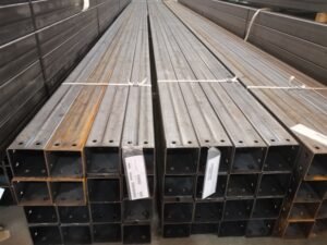
Square Torque Tubes
Common Standards: ASTM A500 Gr.B / Gr.C, EN 10219 S235JR, GB/T Q355B
Process: Cold forming and high-frequency electric welding
Advantages: High bending resistance and hardness
Good stability, suitable for heavy-load systems.
Limitations: Higher wind resistance due to square cross-section; lower material utilization.
Suitable for medium-sized PV power plants
Dimension range: 100×100 – 200×200 mm; Wall thickness: 3.0 – 8.0 mm
| Size (mm) | Wall Thickness (mm) | Weight (kg/m) | Steel Grade | Length (m) |
| 100×100 | 3.0 – 5.0 | 9.0 – 15.5 | Q235 / Q355 | 6 – 12 |
| 120×120 | 3.0 – 6.0 | 11.0 – 21.0 | S355 / Q355 | 6 – 12 |
| 130×130 | 3.5 – 6.0 | 13.5 – 24.5 | Q355 / A500 | 6 – 12 |
| 150×150 | 4.0 – 6.0 | 16.0 – 30.0 | S355 / A572 | 6 – 12 |
| 180×180 | 4.5 – 8.0 | 21.0 – 40.0 | A572 / S355 | 6 – 12 |
| 200×200 | 5.0 – 8.0 | 25.0 – 45.0 | A572 / Q355 | 6 – 12 |
Octagonal Torque Tube- Size Charts
Common Standards: ASTM A500 Gr.B / Gr.C, ASTM A572, EN 10219 S355, GB/T Q355B
Process: Precision roll forming, high-frequency electric welding
Advantages: Optimal torsional resistance
Uniform stress distribution, reducing structural deformation
High compatibility with tracking systems
Applications: High-wind-speed regions, desert power plants, large-scale ground-mounted power plants
Dimension Range: Diagonal Dimensions: 100 – 160 mm, Wall Thickness: 3.0 – 6.0 mm
| Across Flats (mm) | Wall Thickness (mm) | Weight (kg/m) | Steel Grade | Length (m) |
| 100 | 3.0 – 4.0 | 8.5 – 12.5 | Q355 / A500 | 6 – 12 |
| 110 | 3.0 – 4.5 | 9.8 – 14.8 | S355 / A572 | 6 – 12 |
| 120 | 3.0 – 5.0 | 10.5 – 18.0 | Q355 / A500 | 6 – 12 |
| 130 | 3.5 – 5.0 | 12.8 – 20.5 | S355 / A572 | 6 – 12 |
| 140 | 4.0 – 6.0 | 16.2 – 26.5 | Q355 / S355 | 6 – 12 |
| 150 | 4.0 – 6.0 | 18.5 – 30.0 | A572 / S355 | 6 – 12 |
| 160 | 5.0 – 6.0 | 23.8 – 36.0 | A572 / Q355 | 6 – 12 |
Overall, all pipe shapes have their respective advantages and disadvantages. We need to select the appropriate Solar Torque Tube type based on the operating environment, service life, and project scale. In terms of torsional resistance, the order from highest to lowest is: octagonal, rectangular, and circular. Please contact us if you have any questions regarding selection.
Common Standards for Solar Torque Tubes
Different standards specify different performance characteristics. Depending on the type of steel selected and the manufacturing process used, different steel tubes are produced. Below is an overview of the mechanical properties of solar torque tubes under various standards.
| Standard | Grade | Yield Strength (MPa) | Tensile Strength (MPa) | Elongation (%) | Strength Level | Typical Use in Solar Torque Tube |
| ASTM | A500 Gr.B | ≥ 315 | ≥ 400 | ≥ 23% | Medium | General solar structures |
| ASTM | A500 Gr.C | ≥ 345 | ≥ 425 | ≥ 21% | High | Utility-scale tracking systems |
| ASTM | A572 Gr.50 | ≥ 345 | 450 – 620 | ≥ 18% | High | Heavy-duty / high wind areas |
| EN | S235JR | ≥ 235 | 360 – 510 | ≥ 26% | Low | Light structures / low load systems |
| EN | S355JR | ≥ 355 | 470 – 630 | ≥ 22% | High | Mainstream solar torque tubes |
| EN | S355J2 | ≥ 355 | 470 – 630 | ≥ 22% | High | Cold climate / high requirement projects |
| JIS | STKR400 | ≥ 245 | ≥ 400 | ≥ 23% | Medium | Basic structural applications |
| JIS | STKR490 | ≥ 325 | ≥ 490 | ≥ 23% | High | Industrial / higher strength systems |
| GB/T | Q235B | ≥ 235 | 370 – 500 | ≥ 26% | Low | Economy solar structures |
| GB/T | Q355B | ≥ 355 | 470 – 630 | ≥ 21% | High | Main solar torque tube standard |
- Yield strength is the key parameter for structural design in solar torque tubes
- Higher-strength steel is preferred for large-scale utility-scale solar tracking systems
- Q355B / S355JR / ASTM A500 Gr. C are the most commonly used grades globally
- Material selection depends on wind load, span length, and tracker system design
Solar Torque Tube Torsional Load Capacity
In photovoltaic mounting systems, the Solar Torque Tube serves as the core load-transferring component. The primary forces acting on it include torsional torque, bending moment, axial load, and wind load. The formula for calculating torsional load capacity is as follows:
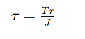
τ = Shear stress (MPa)
T = Torque (N·mm or kN·m)
r = Outer radius of the tube (mm)
J = Polar moment of inertia (mm⁴)
Steel Grade Selection:S235JR → Basic grade, S355JR / S355J2 → Mainstream, Q355B / Q420 → High-strength, ASTM A500 Gr.B / Gr.C.
Common Torque Capacity Ranges
Common Torque Capacity Ranges
Small-scale tracking systems
· Torque range: 1 – 5 kN·m
· Pipe diameter: Ø60 – Ø120 mm
· Wall thickness: 2.0 – 4.0 mm
Medium-scale utility-scale power plants
Torque range: 5 – 20 kN·m
Pipe diameter: Ø120 – Ø200 mm
Wall thickness: 3.0 – 6.0 mm
Large-scale projects in high-wind areas (desert / coastal)
Torque range: 20 – 60 kN·m
Pipe diameter: Ø180 – Ø300 mm
Wall thickness: 5.0 – 10.0 mm
Extra-large tracking systems (high-load design)
Torque range: 60 – 120+ kN·m
Pipe diameter: Ø250 – Ø400 mm
Wall thickness: 8.0 – 16.0 mm
Surface Treatment of Solar Torque Tube
Zinc coating thickness: 65–100 μm (standard); 100–120 μm for projects with high requirements
Service life: 20–30 years
Suitable environments: Desert regions with high temperatures and strong winds, coastal areas with high corrosion, high-humidity environments, and large-scale ground-mounted power plants.
Features: Strong adhesion of the zinc coating; retains corrosion resistance even with minor scratches. Moderate cost.
Zinc coating thickness: 20–30 μm
Service life: 8–15 years
Suitable environments: Regions with relatively mild climates, or temporary structures
Limitations: No zinc coating at cut edges, making them prone to corrosion. Not suitable for long-term exposure to corrosive environments; relatively low stability.
Coating thickness: 60–120 μm
Generally used as a supplementary protective layer.
Features: Attractive appearance with customizable colors; good initial corrosion resistance.
Disadvantages: Poor impact resistance; prone to aging under UV exposure; not used alone; requires combination with other corrosion protection methods.
Corrosion protection is a challenge faced by all pipelines. It is important to note that when the protective coating is applied to the pipe’s outer diameter, it must not compromise the pipe’s overall dimensions or performance. The weld zones require secondary protection.
Applications Solar Torque Tube

Large-Scale Ground-Mounted Solar Power Plants
For projects ranging from 10 MW to 500 MW+, single-axis or dual-axis tracking systems can be employed, with torque tubes serving as main beams running through the entire array of modules. This ensures synchronized movement of the entire array, improves solar radiation capture efficiency, and reduces the risk of structural fatigue.

PV Tracking Mounts
When used as a drive shaft, the torque tube enables ±45° to 60° adjustment, minimizes deformation, and offers a service life exceeding 25 years.

PV Carports
In these projects, the Solar Torque Tube is typically available in round or square tubing. The tubing features moderate strength and excellent corrosion resistance, with an aesthetically pleasing appearance and sufficient load-bearing capacity.

Agricultural PV Systems
This application demands high corrosion resistance from the Solar Torque Tube, as it operates for extended periods in high-humidity, highly corrosive environments. It must also adapt to complex terrain.
FAQ
Advantages of Solar Torque Tube
Increased Power Generation
Improved Utilization of Sunlight Incidence Angles
· Single-axis tracking: +15% to 20%
· Dual-axis tracking: +20% to 25%
Highly Stable Structure
· No deformation under large spans
· No fatigue failure during long-term operation
· Ensures neat module alignment
Excellent Wind Resistance
· Design wind resistance: 35–45 m/s
· Up to 50 m/s+ in extreme regions
Reduces sway and prevents module damage