
Welcome to ALLLAND Steel Pipe Co., Ltd.
ALLLAND Steel Pipe Supply
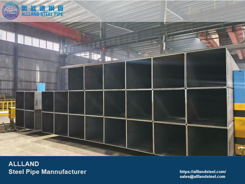
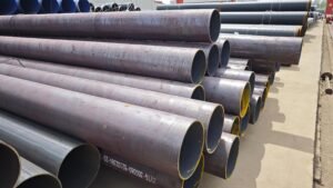
Welcome to ALLLAND Steel Pipe Manufacturing. We offer cold-formed structural hollow sections that comply with the EN 10219 standard, providing cost-effective structural steel solutions for a wide range of engineering projects. Additionally, ALLLAND can provide a variety of steel grades—including S235JRH, S275J0H, and S355J2H—as well as corresponding specifications and dimensions to meet your project requirements. Throughout the entire production process, right up to product delivery, we maintain strict control over product dimensions and quality to ensure consistency and reliability.
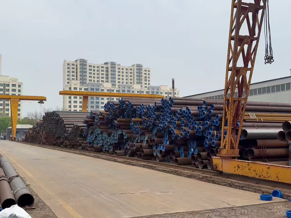
Alllandsteel is a steel pipe manufacturer based in China with 25 years of experience.
The facility spans 22,000 square meters, represents a RMB 700 million investment, and operates four production lines (JCOE, ERW, SMLS, SSAW) alongside five coating lines.
With an annual production capacity of 250,000 tons, the factory covers specifications ranging from Ø406 to Ø1524 and holds multiple international certifications (API/ASTM/EN/ISO/JIS). Focused on steel pipes, creating value for you!
HOT PRODUCTS
POPULAR ARTICLES
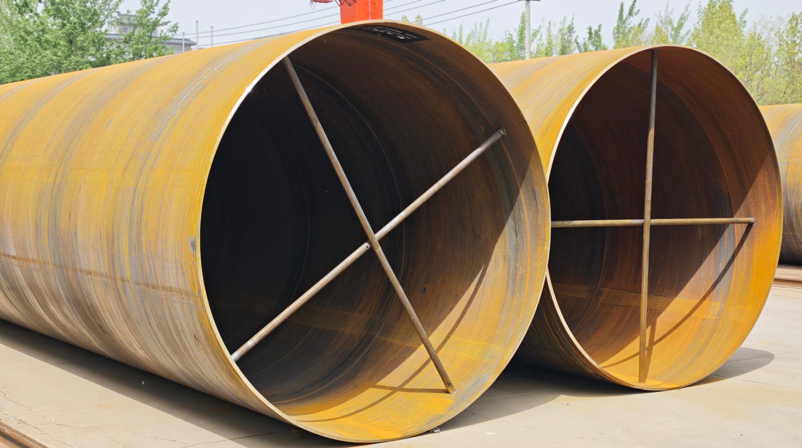
EN 10219 is a European technical standard for cold-formed welded structural hollow sections.
It applies to cold-formed welded structural hollow sections, including circular hollow sections (CHS), square hollow sections (SHS), rectangular hollow sections (RHS), and elliptical hollow sections, and is primarily used in structural engineering applications such as building structures, infrastructure, and industrial applications.
O.D.:
21.3 mm – 610 mm (common)
W.T.:
1.5 mm – 20 mm
Length:
3–20 m, customizable
Manufacturing Process:
Cold Formed-ERW / HFW
Standard Components:
EN 10219-1: Technical Delivery Condition
EN 10219-2: Dimensions & Tolerances
EN 10219-3: Section Properties
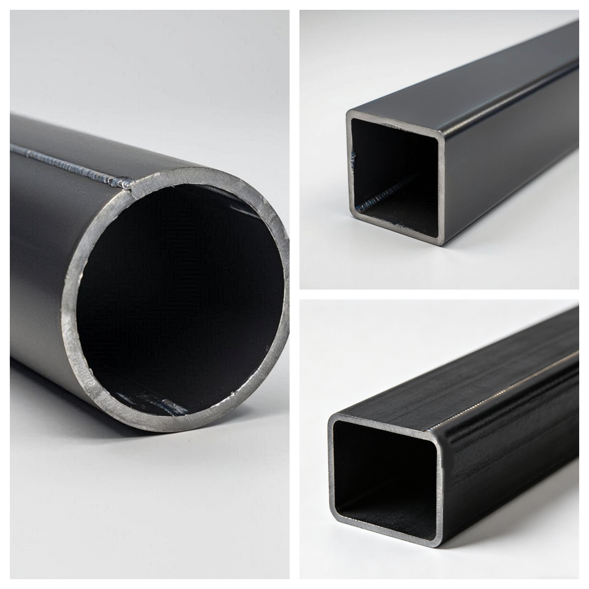
Cross-sectional shape:
Circular Hollow Section (CHS)
Square Hollow Section (SHS)
Rectangular Hollow Section (RHS)
Customized hollow sections: Oval Hollow Section (OHS)
This standard consists of three parts:
EN 10219 steel tubes are classified as cold-formed welded steel tubes and are typically manufactured using the ERW (Electric Resistance Welding) or HFW (High Frequency Welding) process.
1. Raw Material Preparation: Hot-rolled steel coil/strip
2. Uncoiling and Leveling
3. Cold Forming: Multi-pass roll forming; no heating; mechanical cold bending.
4. Welding Process: ERW (Electric Resistance Welding) / HFW (High Frequency Welding).
5. Weld Seam Treatment
6. Sizing & Straightening
7. Cutting
Compared to hot-formed steel tubes, EN 10219 uses a cold-forming process, which is cost-effective and suitable for high-volume production. However, residual stresses resulting from cold forming must be taken into account in engineering applications.
The steel grades in EN 10219 are primarily defined by EN 10219-1, and the designations follow specific naming conventions.
Take S355J2H as an example:
S: Structural steel
355: Minimum yield strength (in MPa)
J2: Impact test temperature
JR: Impact at room temperature (20°C) ≥ 27 J.
J0: Impact at 0°C ≥ 27 J.
J2: Impact at -20°C ≥ 27 J.
H = Hollow section
N: Normalized rolled (fine-grained, impact at -20°C ≥ 40 J)
M: Thermomechanically rolled (better weldability)
K2: Impact at -20°C ≥ 40 J (higher requirement than J2)
1. Non-alloy structural steels
This is the most commonly used and widely supplied grade of steel, including:
· S235JRH
· S275J0H / S275J2H
· S355J0H / S355J2H
| Grade | Yield Strength (MPa) | Common Applications |
| S235 | ≥235 | Lightweight structures |
| S275 | ≥275 | General structures |
| S355 | ≥355 | Heavy-duty structures |
2. Fine-Grained Structural Steels
This type of steel is used for projects requiring higher strength or meeting more stringent specifications. Common grades include:
· S420MH
· S460MH
· S275NH
· S355NH
It offers higher strength and better weldability, making it suitable for large-scale structural projects.
The dimensional specifications for EN 10219 steel tubes are based on EN 10219-2.
Common outer diameters and wall thicknesses for CHS (Circular Hollow Section) tubes
| OD (mm) | WT (mm) |
| 21.3 | 1.6 – 3.2 |
| 26.9 | 1.6 – 3.2 |
| 33.7 | 1.6 – 4.0 |
| 42.4 | 1.6 – 4.5 |
| 48.3 | 1.6 – 5.0 |
| 60.3 | 1.6 – 6.3 |
| 76.1 | 2.0 – 8.0 |
| 88.9 | 2.0 – 8.8 |
| 114.3 | 2.0 – 10.0 |
| 139.7 | 3.0 – 12.5 |
| 168.3 | 3.0 – 12.5 |
| 219.1 | 4.0 – 16.0 |
| 273.0 | 4.0 – 16.0 |
| 323.9 | 5.0 – 20.0 |
| 355.6 | 6.0 – 20.0 |
| 406.4 | 6.0 – 20.0 |
| 508.0 | 6.0 – 20.0 |
Common Size Ranges for SHS (Square Hollow Section) Tubing
| Dimensions (mm) | WT (mm) |
| 20×20 | 1.5 – 3.0 |
| 25×25 | 1.5 – 3.0 |
| 30×30 | 1.5 – 3.5 |
| 40×40 | 1.5 – 4.0 |
| 50×50 | 1.5 – 5.0 |
| 60×60 | 2.0 – 5.0 |
| 80×80 | 2.0 – 6.0 |
| 100×100 | 2.0 – 8.0 |
| 120×120 | 3.0 – 10.0 |
| 150×150 | 3.0 – 12.5 |
| 200×200 | 5.0 – 16.0 |
| 250×250 | 6.0 – 16.0 |
| 300×300 | 6.0 – 20.0 |
| 400×400 | 8.0 – 20.0 |
Common Size Ranges for Rectangular Hollow Sections (RHS)
| Dimensions (mm) | WT(mm) |
| 40×20 | 1.5 – 3.0 |
| 50×25 | 1.5 – 3.5 |
| 60×40 | 1.5 – 4.0 |
| 80×40 | 2.0 – 5.0 |
| 100×50 | 2.0 – 6.0 |
| 120×60 | 2.0 – 6.3 |
| 150×100 | 3.0 – 8.0 |
| 200×100 | 4.0 – 10.0 |
| 250×150 | 5.0 – 12.5 |
| 300×200 | 6.0 – 16.0 |
| 400×200 | 6.0 – 20.0 |
| 500×300 | 8.0 – 20.0 |
Tolerances on shape, straightness and mass
| Characteristic | Circular hollow sections | Square and rectangular hollow sections | Elliptical hollow section | |
Side length mm | Tolerance | |||
| Outside dimensions (D, B and H) | ±1 % with a minimum of + 0,5 mm and a maximum of ±10 mm | H,B<100 100≤H,B≤200 H,B>200 | ±1% with a minimum of +0,5 mm ±0,8% +0,6% | ±1% with a minimum of ± 0,5 mm |
| Thickness (T) | For D≤ 406,4 mm: T>5mm±10% T> 5 mm +±0,5 mm For D>406,4 mm:±10% with a maximum of ±2 mm | T≤5mm±10% T>5 mm±0,5 mm | T≤5mm±10% T>5 mm±0,5 mm | |
| Out-of-roundness (O) | 2 % for hollow sections having a diameter to thickness ratio not exceeding100a | – | – | |
| Concavity/ convexity (x1, x2)b | – | Max. 0,8% with a minimum of 0,5 mm | – | |
| Squareness of side | – | 90°±1% | – | |
| Twist (V) | – | 2 mm plus 0,5 mm/m length | – | |
| Straightness (e) | 0,20 % of total length and 3 mm over any 1 m length | 0,15 % of total length and 3 mm over any 1 m length | 0,2 % pf total length and 3 mm over any 1 m length | |
| Mass oer unit length (M) | ±6% on individual delivered lengths | |||
a When the diameter to thickness ratio exceeds 100, application of tolerance on out-of-roundness is not required, unless specifically agreed. b The tolerance on convexity and concavity is independent of the tolerance on outside dimensions. | ||||
Tolerance on external corner profiles
| Thickness T | External corner profile C1, C2 or Ra |
T≤6 6<T≤10 10<T | 1,6T to 2,4T 2,0T to 3,0 T 2,4T to 3,6T |
| a The sides need not be tanential to the corner arcs. | |
Tolerances on manufacturer’s delivered length
| Dimensions in mm | ||
| Type of length a | Range of length or length L | Tolerance |
| Random length | 4 000< L ≤16 000 with a range of2 000 per order item | 10 % of sections supplied may be below the minimum for the ordered range but not shorter than 75 % of the minimum range length |
| Approximate length | ≥4000 | +50/0 mm |
| Exact length b | <6000
6000≤0≤10000
>10000 | +10/0 mm
+15/0 mm
+5/0 mm + 1 mm/m |
a The manufacturer shall establish at the time of enquiry and order the type of length required and the length range or length.
b Common lengths available are 6 m and 12 m.
A key parameter in EN 10219 is the Carbon Equivalent (CEV).
CEV = C + Mn/6 + (Cr + Mo + V)/5 + (Ni + Cu)/15
The carbon equivalent is used to control the weldability of steel pipes and prevent cracks from forming during or after welding.
| Element | Permissible maximum content in the cast analysis % by mass | Permissible deviation of the product analysis from specified limits for the cast analysis % by mass |
| C* | ≤0.20 | +0.02 |
| >0.20 | +0.03 | |
| Si | ≤0.60 | +0.05 |
| Mn | Non-alloy ≤1.60 | +0.10 |
| Fine grain ≤1.70 | -0.05 +0.10 | |
| P | Non-alloy ≤0.040 | +0.010 |
| Fine grain ≤0.035 | +0.005 | |
| S | Non-alloy ≤0.040 | +0.010 |
| Fine grain ≤0.030 | +0.005 | |
| Nb | ≤0.050 | +0.010 |
| V | ≤0.20 | +0.02 |
| Ti | ≤0.05 | +0.01 |
| Cr | ≤0.30 | +0.05 |
| Ni | ≤0.80 | +0.05 |
| Mo | ≤0.20 | +0.03 |
| Cu | ≤0.35 | +0.04 |
| ≤0.35<Cu≤0.70 | +0.07 | |
| N | ≤0.025 | +0.002 |
| Atotal | ≥0.020 | -0.005 |
| * For S235JRH in thicknesses≤16mm, the peimissible deviation = 0.4% C, and for thicknesses > 16 mm and ≤40 mm the permissible deviation = 0.05 % C. | ||
S235JRH is a low-carbon steel with a relatively low manganese content. While its strength is not particularly high, it offers the lowest cost and the best weldability, making it suitable for light-duty structures and certain temporary structures.
S355J0H / J2H is the most commonly used steel grade in engineering. Its carbon content is strictly controlled, and the manganese content is increased to enhance strength.
While offering high strength, it also provides good weldability and is widely used in steel structure buildings, bridges, industrial plants, and other fields.
Mechanical properties of non-alloy steel hollow sections in thicknesses ≤ 40 mm
| Steel grade | Yield Strength, ReHMpa | Tensile Strength, RmMpa | Minimum Elongation, A% | Minimum impact energy KVeJ | |||||
| Steel name | Steel number | Specified thicknessmm | Specified thicknessmm | Specified thicknessmm | at test temperature of | ||||
| ≤ 16 | > 16 ≤ 40 | < 3 | ≥ 3 ≤ 40 | ≤ 40 | -20°C | 0 °C | 20 °C | ||
| S235JRH | 1.0039 | 235 | 225 | 360-510 | 360-510 | 24 b | – | – | 27 |
| S275J0H | 1.0149 | 275 | 265 | 430-580 | 410-560 | 20 c | – | 27 | – |
| S275J2H | 1.0138 | 27 | – | – | |||||
| S355J0H | 1.0547 | 355 | 345 | 510-680 | 470-630 | 20 c | – | 27 | – |
| S355J2H | 1.0576 | 27 | – | – | |||||
| S355K2H | 1.0512 | 40d | – | – | |||||
a The impact properties are verified only when Option 1.3 is specified. b For thicknesses > 3 mm and section sizes D/T < 15 (round) and (B+H)/2T < 12,5 (square and rectangular) the minimum elongation is reduced by 2. For thicknesses ≤ 3 mm the minimum value for elongation is 17 %. c For section sizes D/T < 15 (circular) and (B+H)/2T < 12,5 (square and rectangular) the minimum elongation is reduced by 2. d This value corresponds to 27J at –30 °C (see EN 1993-1-1). | |||||||||
Cold-formed welded hollow sections, as defined by the EN 10219 standard, are widely favored in applications such as structural steel, non-pressure piping, and load-bearing components due to their cost-effectiveness, weldability, and high dimensional accuracy.
Steel Structures
· Industrial buildings
· Commercial buildings
· Stadium structures
S355J2H offers high strength, is suitable for on-site welding, and is easy to install, making it a common choice in the above applications.
Infrastructure and Bridge Engineering (Bridge Construction)
EN 10219 can be customized in length and cross-section, and when combined with paint coating or hot-dip galvanizing, it better withstands outdoor corrosive environments.
· Bridge support structures
· Municipal facilities
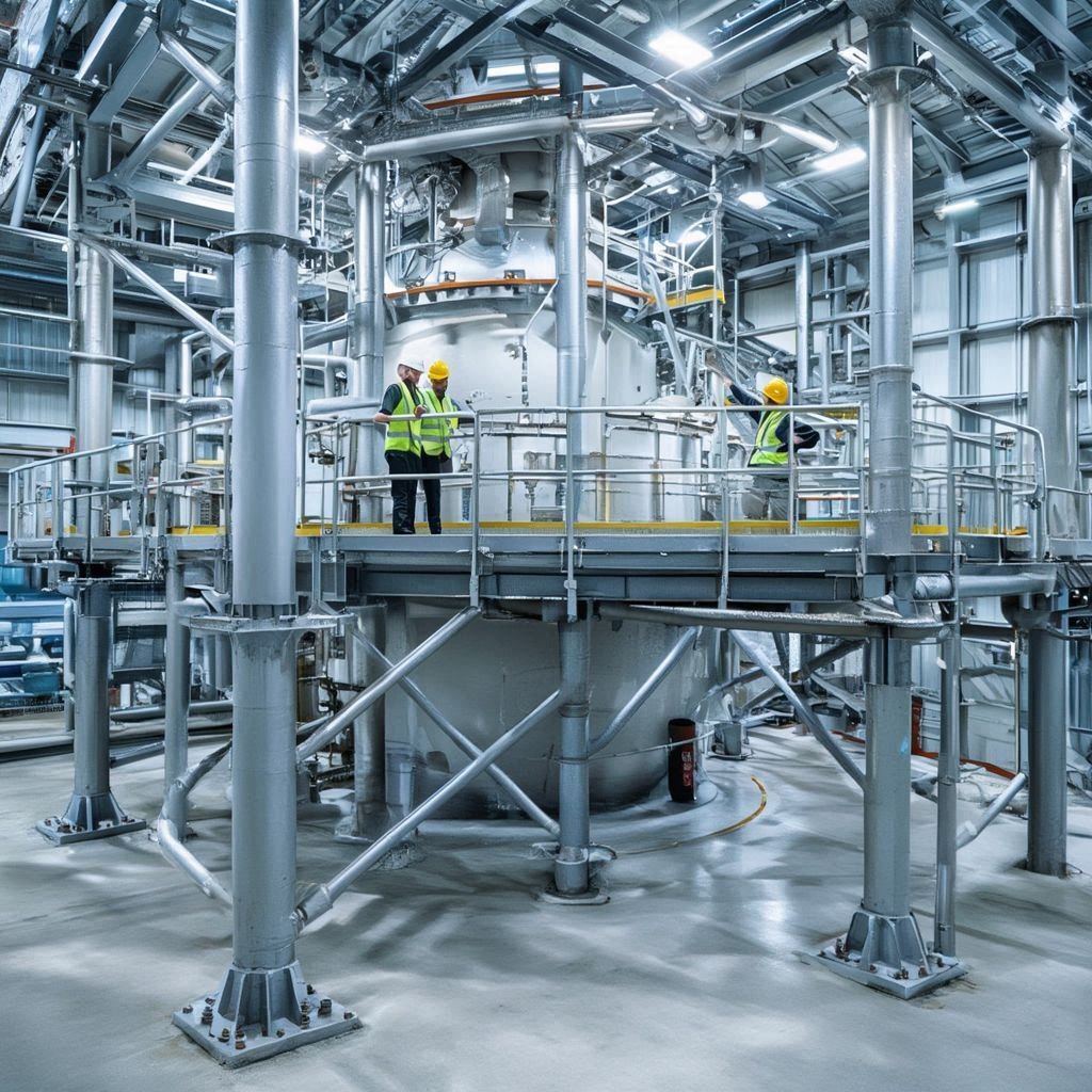
Industrial Equipment Structures (Industrial Equipment)
EN 10219 features strict dimensional accuracy control with minimal tolerances and is easy to machine.
· Machine frames
· Conveyor supports
· Factory platforms
Offshore & Energy
· Offshore platform auxiliary structures
· Wind energy structures
· Oil and gas auxiliary structures
| Manufacturing Process | EN 10219 | EN 10210 |
| Welding after cold-forming at room temperature. | Hot-rolled or extruded at high temperatures (>900°C) | |
| Core Advantages | High dimensional accuracy, excellent surface quality, cost-effective, lightweight. | Excellent toughness and impact resistance; free of internal stress; suitable for heavy-duty applications. |
| Typical Applications | Light- to medium-duty structures, building curtain walls, mechanical frames, aesthetic components. | Heavy-duty load-bearing structures, bridge main girders, and structures with high seismic and fatigue resistance. |
| Cost and Precision | Lower cost, tight dimensional tolerances, smooth surface. | Higher cost, with average dimensional tolerances and surface finish. |
If a project prioritizes cost-effectiveness and dimensional accuracy, EN 10219 is the recommended choice; if a project requires impact toughness, high load-bearing capacity, or the ability to operate in harsh environments, EN 10210 should be considered.
Fill in the form below and our team will be happy to assist you


