
Welcome to ALLLAND Steel Pipe Co., Ltd.
ALLLAND Boiler Steel Pipe Supply
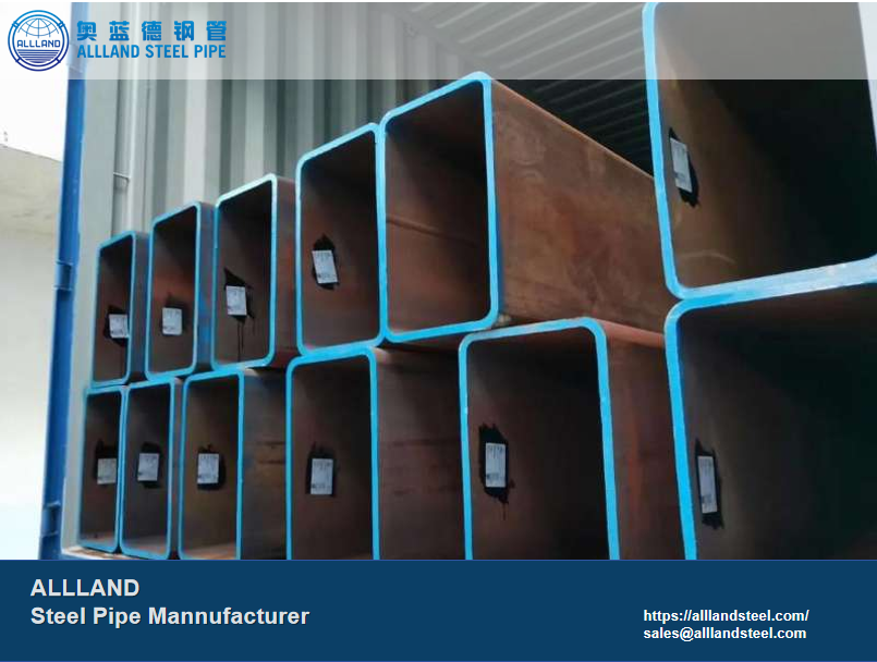
Welcome to ALLLAND Steel Pipe Factory. We specialize in manufacturing high-quality Rectangular Hollow Sections (RHS), widely used in construction, bridge engineering, mechanical engineering, and industrial steel structures. We produce standard sizes according to EN 10219, EN 10210, ASTM A500, and GOST standards. For custom specifications, please contact us. Rectangular Hollow Section pipes offer significant advantages for projects subjected to unidirectional forces by effectively controlling construction costs. ALLLAND provides surface treatment services including galvanized coatings, chamfering, and beveling. Contact us for your requirements.
Alllandsteel is a steel pipe manufacturer based in China with 25 years of experience. The facility spans 22,000 square meters, represents a RMB 700 million investment, and operates four production lines (JCOE, ERW, SMLS, SSAW) alongside five coating lines. With an annual production capacity of 250,000 tons, the factory covers specifications ranging from Ø406 to Ø1524 and holds multiple international certifications (API/ASTM/EN/ISO/JIS). Focused on steel pipes, creating value for you!
HOT PRODUCTS
POPULAR ARTICLES
Rectangular Hollow Section (RHS) is a type of hollow section primarily used in structural construction and load-bearing systems, generally not intended for fluid transport. Unlike circular hollow sections, Rectangular Hollow Sections are suitable for engineering applications with specific directional forces. They exhibit different load-bearing capacities along their long and short sides. Along the stronger axis, they offer superior bending and torsional resistance, making them ideal for structures subjected to unidirectional forces, such as beams, bridges, and frames.
O.D.:
40 × 20 mm ~ 500 × 300 mm
W.T.:
1.6 mm to 25 mm
Length:
6 m / 12 m / Custom Length
Process:
Welded
Standards:
EN 10219/10210, ASTM A500/A53, DIN 2395 / DIN 2391
Steel Grades:
S235 / S275 / S355, ASTM A500 Gr.B / Gr.C, Q235 / Q355 / 09G2S
Surface Treatment:
Black pipe, Hot-dip galvanized, Sandblasted, Corrosion-resistant
Corrosion Protection Standards:
DIN 30670/30671, ISO 1461
Rectangular Hollow Section Manufactured by ALLLAND
Below is the size chart for Rectangular Hollow Sections, which includes pipe dimensions and weights for various specifications. For each pipe size, the weight per foot, as well as the weights for 6m and 12m lengths, are provided. These weights are theoretical values; actual weights may vary.
| Dimensions (Width x Height x Wall Thickness) mm | Theoretical Weight kg/m | ||
| Per Foot | 6 m | 12 m | |
| 15 × 15 × 1.50 | 1.28 | 4.21 | 8.42 |
| 20 × 20 × 1.50 | 1.71 | 5.61 | 11.22 |
| 20 × 20 × 2.00 | 2.28 | 7.48 | 14.96 |
| 20 × 20 × 2.50 | 2.90 | 9.5 | 19 |
| 25 × 25 × 1.50 | 2.14 | 7.02 | 14.04 |
| 25 × 25 × 2.00 | 2.85 | 9.36 | 18.72 |
| 25 × 25 × 2.50 | 3.60 | 11.8 | 23.6 |
| 40 × 20 × 2.00 | 0.51 | 1.68 | 3.36 |
| 40 × 20 × 2.50 | 0.62 | 2.03 | 4.06 |
| 40 × 20 × 3.00 | 0.72 | 2.36 | 4.72 |
| 50 × 25 × 2.00 | 0.67 | 2.21 | 4.42 |
| 50 × 25 × 2.50 | 0.83 | 2.72 | 5.44 |
| 50 × 25 × 3.00 | 0.98 | 3.22 | 6.44 |
| 50 × 30 × 2.50 | 0.89 | 2.92 | 5.84 |
| 50 × 30 × 3.00 | 1.05 | 3.45 | 6.9 |
| 50 × 30 × 4.00 | 1.36 | 4.46 | 8.92 |
| 60 × 40 × 2.50 | 1.13 | 3.71 | 7.42 |
| 60 × 40 × 3.00 | 1.34 | 4.39 | 8.78 |
| 80 × 40 × 2.50 | 1.30 | 4.26 | 8.52 |
| 80 × 40 × 4.00 | 2.12 | 6.97 | 13.94 |
| 100 × 50 × 2.50 | 1.72 | 5.63 | 11.26 |
| 100 × 50 × 3.00 | 2.06 | 6.75 | 13.5 |
| 100 × 50 × 4.00 | 2.70 | 8.86 | 17.72 |
| 100 × 50 × 5.00 | 3.32 | 10.9 | 21.8 |
| 100 × 60 × 3.60 | 2.62 | 8.59 | 17.18 |
| 120 × 80 × 2.50 | 2.33 | 7.65 | 15.3 |
| 250 × 150 × 10 | 17.92 | 58.8 | 117.6 |
| 250 × 150 × 12 | 21.21 | 69.6 | 139.2 |
| 250 × 150 × 16 | 27.52 | 90.3 | 180.6 |
| 260 × 180 × 8 | 16.06 | 52.7 | 105.4 |
| 260 × 180 × 12 | 23.53 | 77.2 | 154.4 |
| 300 × 200 × 8 | 18.38 | 60.3 | 120.6 |
| 300 × 200 × 12 | 26.97 | 88.5 | 177 |
| Steel Grade | Yield Strength (MPa) | Tensile Strength (MPa) | Applicable Structural Grade |
| S235 / Q235 | ≥235 | 360–510 | Lightweight Structures |
| S275 | ≥275 | 410–560 | Medium Load |
| S355 / Q355 | ≥355 | 470–630 | Medium-High Load |
| A500 Gr.C | ≥317 | ≥427 | High-Strength Structures |
| 09G2S | ≥290 | 430–580 | Low-Temperature Structures |
Unlike other cross-sectional shapes, rectangular sections can customize their length-to-width ratio based on specific environmental and loading conditions to maximize material savings. Below, we outline application scenarios for different length-to-width ratios and their respective functions and advantages.
Unlike the uniform stress distribution in rectangular and circular sections, square sections exhibit differing stresses along their length and width:
The strong axis bears bending loads; the weak axis controls deformation. Therefore, by controlling the length and width of square sections, they can be applied in various scenarios.
Below are several application references:
Industrial Plant Steel Structures:
The strong axis bears compressive forces, while the weak axis provides excellent stability, reducing lateral deformation.
Common specifications: 200 × 100 × 6 mm / 250 × 150 × 8 mm (S355 / Q355).
Bridge Steel Structures:
Height acts as the strong axis, bearing bending moments, while width controls lateral vibration and deformation.
Common dimensions: 330×200×8, 400 × 250×10
Exterior Wall Support Systems:
The strong axis controls deflection, while the weak axis manages wind-induced vibrations and torsional forces.
Common specifications: 100 × 50 × 4 mm, 150 × 75 × 5 mm
Cross-sectional area directly influences load-bearing capacity and the pipe’s self-weight. A larger cross-sectional area yields higher load-bearing capacity. The calculation formula is:
A = B × H − (B − 2t) × (H − 2t)
B = Width
H = Height
t = Wall Thickness
The moment of inertia represents a section’s resistance to bending about specific axes:
Ix: Around the strong axis (height direction), determining bending strength and deflection control in this direction.
Iy: Around the weak axis (width direction), determining lateral bending, lateral displacement, and stability.
Rectangular Hollow Sections can widen Ix and Iy by adjusting length and width.
Example: 200 × 200 RHS, Ix/Iy = 1; 400 × 200 RHS, Ix/Iy = 4–6. Benefits of widening Ix and Iy:
RHS manufacturing methods include hot forming, cold forming, and welded tubes. Hot-formed tubes feature lower residual stresses and superior plasticity, making them more suitable for high-grade structures.
Different standards specify distinct steel grades, resulting in varying mechanical properties—such as yield strength and tensile strength—which directly dictate their applicable scenarios.
| Standard | Height Range | Width Range | Thickness Range |
| EN 10219 | 40–500 mm | 20–400 mm | 1.5–16 mm |
| EN 10210 | 60–500 mm | 40–400 mm | 3.2–25 mm |
| ASTM A500 | 38–406 mm | 38–305 mm | 1.65–12.7 mm |
| DIN (old) | 40–300 mm | 20–200 mm | 2–12 mm |
| GOST | 40–300 mm | 20–200 mm | 2–14 mm |
EN 10210 → Highest thick-wall capability (up to 25 mm)
EN 10219 → Broadest coverage
ASTM A500 → Imperial system, conservative wall thicknesses
GOST → Focuses on small-to-medium sizes, suitable for low-temperature grades
DIN → Traditional system, now incorporated into EN
When the bending moment direction is clearly defined, single-row deflection needs to be controlled, or cost savings and improved material utilization are required, RHS can be selected.
When the loading direction is uncertain or forces are applied uniformly in all directions, and superior torsional resistance is needed, CHS can be selected.
First, the markets differ: ASTM A500 is the mainstream product standard for the North American market, while EN 10219 is commonly used in the European market. Second, testing requirements vary: ASTM A500 does not mandate impact testing, whereas EN 10219 requires impact testing with specified impact grades (J0, J2). Finally, dimensional control differs, with EN 10219 imposing stricter tolerance controls. Below are the mechanical properties of different steel grades under both standards.
| Grade | Yield Strength | Tensile Strength |
| Gr.B | ≥ 315 MPa | ≥ 400 MPa |
| Gr.C | ≥ 345 MPa | ≥ 450 MPa |
| S235 | ≥ 235 MPa | 360–510 MPa |
| S355 | ≥ 355 MPa | 470–630 MPa |
Fill in the form below and our team will be happy to assist you