
Welcome to ALLLAND Steel Pipe Co., Ltd.
ALLLAND Boiler Steel Pipe Supply
Welcome to ALLLAND. We specialize in manufacturing high-quality Cuplock scaffolding systems and steel tubes. With advanced production equipment and a rigorous quality control system, we provide high-precision scaffolding steel tube products, including vertical poles, horizontal poles, and cross braces, while also offering pre-fabricated components. Our products are manufactured using high-quality steel grades such as Q235 and Q355, ensuring excellent strength, durability, and reliability. They are widely used in construction and industrial projects worldwide.
Alllandsteel is a steel pipe manufacturer based in China with 25 years of experience.
The facility spans 22,000 square meters, represents a RMB 700 million investment, and operates four production lines (JCOE, ERW, SMLS, SSAW) alongside five coating lines.
With an annual production capacity of 250,000 tons, the factory covers specifications ranging from Ø406 to Ø1524 and holds multiple international certifications (API/ASTM/EN/ISO/JIS). Focused on steel pipes, creating value for you!
HOT PRODUCTS
POPULAR ARTICLES
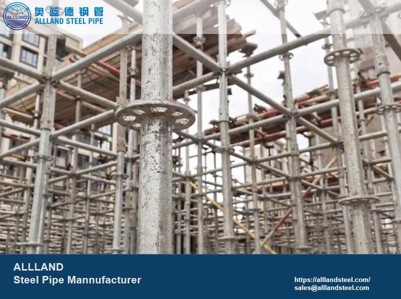
Cuplock Scaffolding is a steel scaffolding system that uses vertical posts as the primary load-bearing elements and is connected via cup-lock joints. Its key feature is the ability to achieve efficient installation and stable connections through pre-engineered joint designs. The cup-lock joints secure multiple horizontal members at a single connection point by rotating and interlocking the upper and lower cups. This mechanical rotation replaces bolted connections, resulting in faster assembly and higher strength.
Below, we will provide an overview of the performance and structure of Cuplock Scaffolding, as well as the properties of Cuplock Scaffolding pipes. Please feel free to contact us with any questions.
Click on the blog to learn more about steel pipe.
O.D.:
48.3 mm (International Standard)
W.T.:
3.0 mm / 3.2 mm / 3.5 mm / 4.0 mm
Length:
0.5 m – 6.0 m (customizable)
Surface treatment:
Galvanized, spray-coated, powder-coated
Standards:
EN 12810 / EN 12811, AS/NZS 1576
Surface treatment thickness:
Galvanized 60–80 μm; Coating thickness: 50–70 μm
Steel grade:
Q235, Q335
Welding Methods:
MIG / MAG / Manual Arc Welding
1. Modular Design
All components are manufactured to standardized designs, making them reusable and freely combinable without any restrictions. This significantly reduces installation time.
2. Cup-Lock Joints
Cup-Lock joints are the most distinctive feature of Cuplock Scaffolding. The lower cup-lock is welded to the upright, allowing for the installation of four horizontal rails. The upper cup serves as a locking mechanism. The cup distributes stress evenly, requires no welding, and, most importantly, provides exceptional stability.
3. High Strength
Cuplock Scaffolding uses high-strength steel pipes specifically designed for scaffolding. It can be used in high-rise construction or harsh environments.
4. High Construction Efficiency
All pipes are pre-fabricated in the factory. Upon delivery, they require no welding or additional processing and can be installed immediately, significantly reducing construction time.
While structural stability is a key advantage of Cuplock Scaffolding, the performance of the steel pipes that make up the scaffolding is even more critical. Without high-strength pipes for support, even the most stable structure would be ineffective. Below, we introduce the Cuplock Scaffolding steel pipes manufactured by our company, including their performance specifications, technical parameters, and the specific applications of pipes in different locations.
These components form the most critical structure of the Cuplock Scaffolding system. The performance characteristics of the steel tubes used in these components determine the scaffolding’s service life and suitable applications.
| Material | Yield Strength | Tensile Strength |
| Q235 | ≥235 MPa | 370–500 MPa |
| Q355 | ≥355 MPa | 470–630 MPa |
Q235:
C ≤ 0.22%
Mn ≤ 1.40%
Si ≤ 0.35%
Q355:
C ≤ 0.20%
Mn ≤ 1.60%
Si ≤ 0.55%
| Item | Standard |
| Outer Diameter | ±0.2 mm |
| Wall Thickness | ±10% |
| Length | ±1 mm |
| Joint Location | ±2 mm |
When installing Cuplock Scaffolding, it is essential to follow the installation manual. Below, we will outline some installation tips and the requirements for installing uprights and horizontal members. Please contact us if you have any questions.
The horizontal member connector must be inserted into the lower cup of the upright, which is secured to the upright, before tightening the upper cup. Install one joint before moving on to the next.
It is important to ensure the joint surfaces are free of oil or grease, and that the connectors do not get jammed. When tightening the upper and lower cups, avoid applying excessive force to prevent damage to the zinc coating on the pipe surface, which could lead to rust.
First, the standard horizontal spacing for horizontal braces is 500 mm.
Second, the angle of diagonal braces should be between 45° and 60°.
Finally, the spacing of the vertical posts must be calculated based on their load-bearing capacity using the following formula:
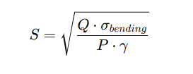
S: Spacing between standards (m)
Q: Section inertia-related parameter of the ledger (reflecting the bending resistance of the steel pipe)
σ_bending: Allowable bending stress (depending on steel grade, such as Q235 or Q355)
P: დიზign load per unit area (kN/m²)
γ: Safety factor
In actual construction, the following data can be used as a reference:
| Platform Applications | Load Class | Standard Spacing (S) |
| General-purpose work platforms | 1.5–2.0 kN/m² | 1.2–2.0 m |
| High-rise building platforms | 2.0–3.0 kN/m² | 1.0–1.5 m |
| Heavy-duty industrial platforms | 3.0–5.0 kN/m² | ≤1.2 m |
It is recommended that the steel tubes used in Cuplock Scaffolding be manufactured by the same supplier to ensure consistency in material properties, tolerances, and spacing. This prevents situations where mixing different brands results in joints that cannot be securely locked.
Final safety performance must be taken into account. The load-bearing capacity of each upright is approximately 10–20 kN. The load-bearing capacity of the crossbars must be calculated based on their wall thickness and span. It is recommended not to pile items in clusters to prevent uneven loading and the risk of collapse.
Fill in the form below and our team will be happy to assist you